VESC – Open Source ESC

Post updated 2016-01-22

About this project

I have made many updates to my custom motor controller recently and the old post is getting confusing with notes and updates, I decided to write a new post about it that hopefully is more clear, more complete and easier to follow. This might sound a bit ambitions, but my goal is to make the best ESC available. I really enjoy sharing knowledge, so I want to keep all the hardware and software open.

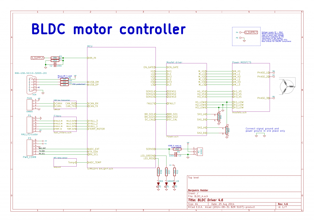
This is an overview of the schematic (download a complete PDF here):

Schematic-1

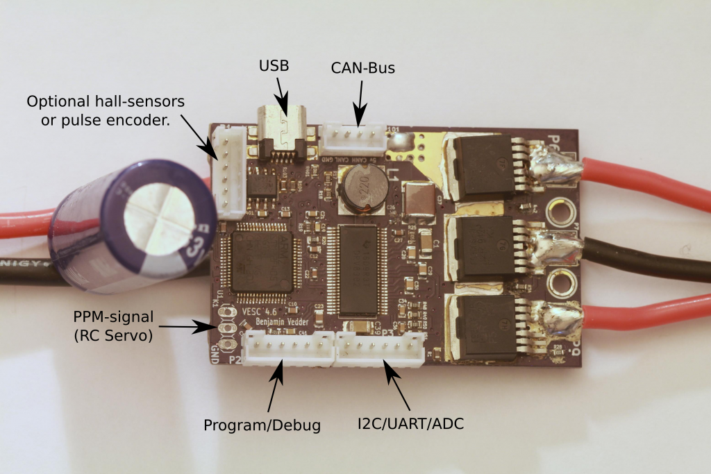
This is the front of the PCB:

PCB_Front

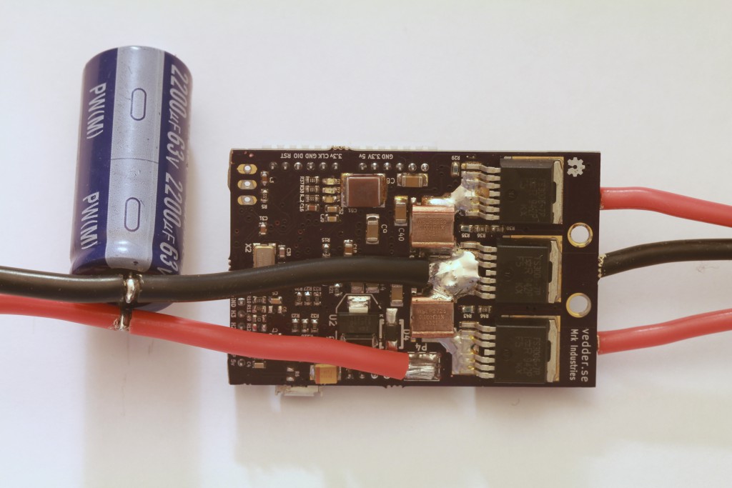
The back:

pcb_back

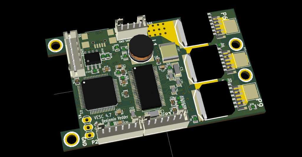
3D render from KiCad:

3D

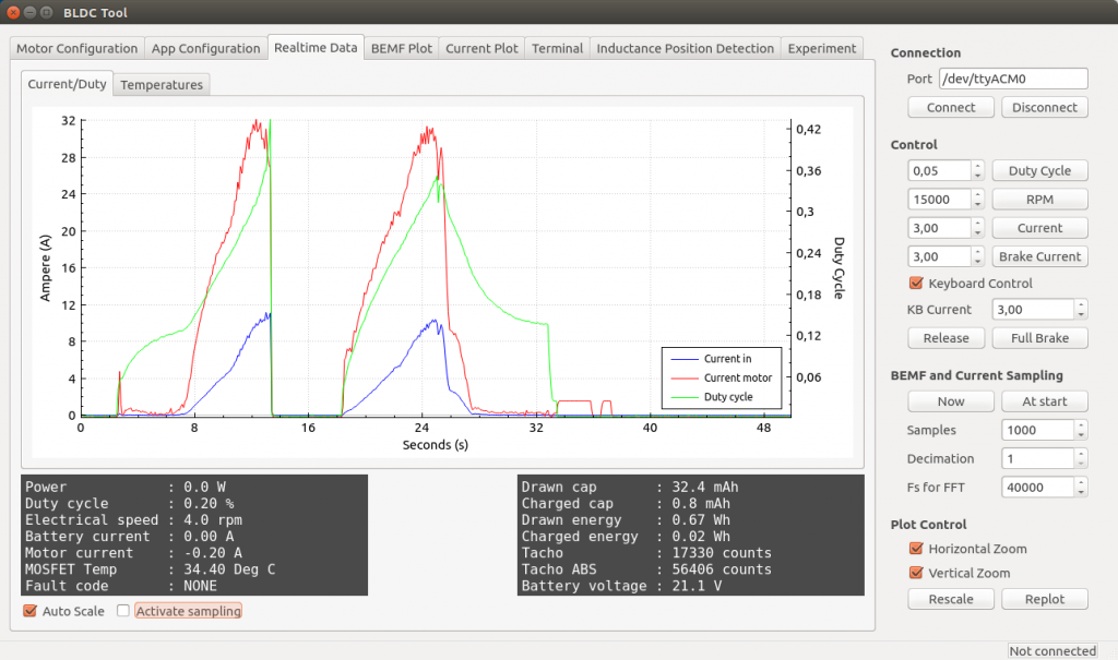
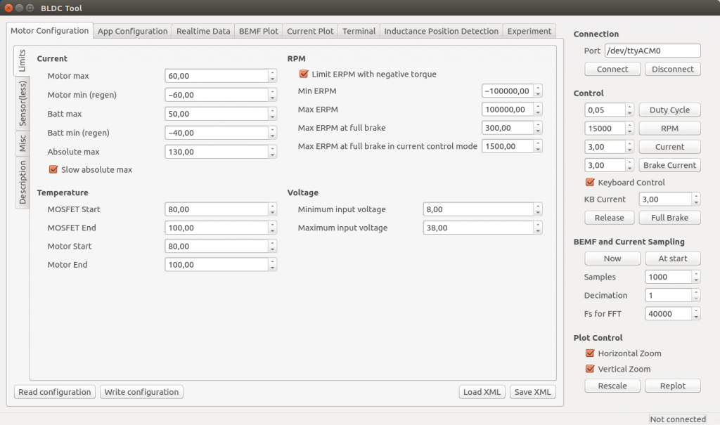
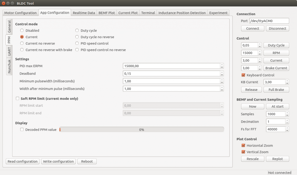
Some screenshots of the configuration GUI (BLDC Tool):

RT_Data

MCCONF_Limits

APP_PPM

Resources

All files are on github to keep them up to date, so check these links on a regular basis:

Related posts

Forums

Because information about the VESC is scattered all over the internet and a lot of information is in email conversations with me, I have created a forum dedicated to the VESC here.

Live Chat

I have created an IRC channel on freenode where you can live chat with me and other users about VESC and my other projects. Feel free to join: http://webchat.freenode.net/?channels=vedder

Features

  • The hardware and software is open source. Since there are plenty of CPU-resources left, the customization possibilities are almost endless.
  • STM32F4 microcontroller.
  • DRV8302 MOSFET driver / buck converter / current shunt amplifier.
  • IRFS7530 MOEFETs (other FETs in the same package also fit).
  • 5V 1A output for external electronics from the buck converter integrated on the DRV8302.
  • Voltage: 8V – 60V (Safe for 3S to 12S LiPo).
  • Current: Up to 240A for a couple of seconds or about 50A continuous depending on the temperature and air circulation around the PCB.
  • Sensored and sensorless FOC wich auto-detection of all motor parameters is implemented since FW 2.3.
  • Firmware based on ChibiOS/RT.
  • PCB size: slightly less than 40mm x 60mm.
  • Current and voltage measurement on all phases.
  • Regenerative braking.
  • DC motors are also supported.
  • Sensored or sensorless operation.
  • A GUI with lots of configuration parameters
  • Adaptive PWM frequency to get as good ADC measurements as possible.
  • RPM-based phase advance (or timing/field weakening).
  • Good start-up torque in the sensorless mode (and obviously in the sensored mode as well).
  • The motor is used as a tachometer, which is good for odometry on modified RC cars.
  • Duty-cycle control, speed control or current control.
  • Seamless 4-quadrant operation.
  • Interface to control the motor: PPM signal (RC servo), analog, UART, I2C, USB  or CAN-bus.
  • Wireless wii nunchuk (Nyko Kama) control through the I2C port. This is convenient for electric skateboards.
  • Consumed and regenerated amp-hour and watt-hour counting.
  • Optional PPM signal output. Useful when e.g. controlling an RC car from a raspberry pi or an android device.
  • The USB port uses the modem profile, so an Android device can be connected to the motor controller without rooting. Because of the servo output, the odometry and the extra ADC inputs (that can be used for sensors), this is perfect for modifying an RC car to be controlled from Android (or raspberry pi).
  • Adjustable protection against
    • Low input voltage
    • High input voltage
    • High motor current
    • High input current
    • High regenerative braking current (separate limits for the motor and the input)
    • Rapid duty cycle changes (ramping)
    • High RPM (separate limits for each direction).
  • When the current limits are hit, a soft back-off strategy is used while the motor keeps running. If the current becomes way too high, the motor is switched off completely.
  • The RPM limit also has a soft back-off strategy.
  • Commutation works perfectly even when the speed of the motor changes rapidly. This is due to the fact that the magnetic flux is integrated after the zero crossing instead of adding a delay based on the previous speed.
  • When the motor is rotating while the controller is off, the commutations and the direction are tracked. The duty-cycle to get the same speed is also calculated. This is to get a smooth start when the motor is already spinning.
  • All of the hardware is ready for sensorless field-oriented control (FOC). Writing the software is the remaining part. However, I’m not sure if FOC will have many benefits for low inductance high-speed motors besides running a bit quieter. Sensored and sensorless FOC is fully implemented since FW 2.3.

Continue reading

A custom BLDC motor controller (a custom ESC)

================= IMPORTANT UPDATE =================

I have written a new post about my open ESC on this page and also updated the hardware significantly. If you haven’t built it yet and if you are planning to order parts for it, please refer to that page. I will only leave this page for reference in case you have built it before I wrote the new post and updated the hardware. Also, If you have built the ESC before, the tutorial and software on the new page also applies to the old hardware.

=====================================================

Updated 2014-12-08

For about three years I have been working on a custom BLDC motor controller (also known as an ESC). I have spent hundreds of hours on writing code and I have made many minor and four major revisions of the printed circuit board (PCB). Now I finally have something that I can publish. The code can still be cleaned up a lot, especially the latest parts that I wrote in a hurry, but I don’t want to delay the release forever.

The features of this BLDC controller are:

  • The hardware and software is open source.
  • A STM32F4 microcontroller.
  • A DRV8302 MOSFET driver / buck converter / current shunt amplifier.
  • IRFS3006 MOEFETs.
  • 5V 1A output for external electronics from the buck converter integrated on the DRV8302.
  • Voltage: 8V – 60V.
  • Current: Up to 240A for a couple of seconds or about 50A continuous depending on the cooling.
  • PCB size: slightly less than 40mm x 60mm.
  • Current and voltage measurement on all phases.
  • Regenerative braking.
  • Sensored or sensorless commutation.
  • Adaptive PWM frequency to get as good ADC measurements as possible.
  • RPM-based phase advance.
  • Good start-up torque in the sensorless mode (and obviously in the sensored mode as well).
  • The motor is used as a tachometer, which is good for odometry on modified RC cars.
  • Duty-cycle control, speed control or current control.
  • Seamless 4-quadrant operation.
  • Interface to control the motor: servo signal, analog, UART, I2C, USB  or CAN (with a transceiver). Some of these modes need a bit more code to work, but not much.
  • Servo signal output. Good when e.g. controlling an RC car from a raspberry pi or an android device.
  • The USB port uses the modem profile, so an Android device can be connected to the motor controller without rooting. Because of the servo output, the odometry and the extra ADC inputs (that can be used for sensors), this is perfect for modifying a RC car to be controlled from Android (or raspberry pi).
  • Adjustable protection against
    • Low input voltage
    • High input voltage
    • High motor current
    • High input current
    • High regenerative braking current (separate limits for the motor and the input)
    • Rapid duty cycle changes (ramping)
    • High RPM (separate limits for each direction).
  • When the current limits are hit, a soft back-off strategy is used while the motor keeps running.
  • The RPM limit also has a soft back-off strategy.
  • The commutation works perfectly even when the speed of the motor changes rapidly. This is due to the fact that the magnetic flux is integrated after the zero crossing instead of adding a delay based on the previous speed.
  • When the motor is rotating while the controller is off, the commutations and the direction are tracked. The duty-cycle to get the same speed is also calculated. This is to get a smooth start when the motor is already spinning.
  • All of the hardware is ready for sensorless field-oriented control (FOC). Writing the software is the remaining part.

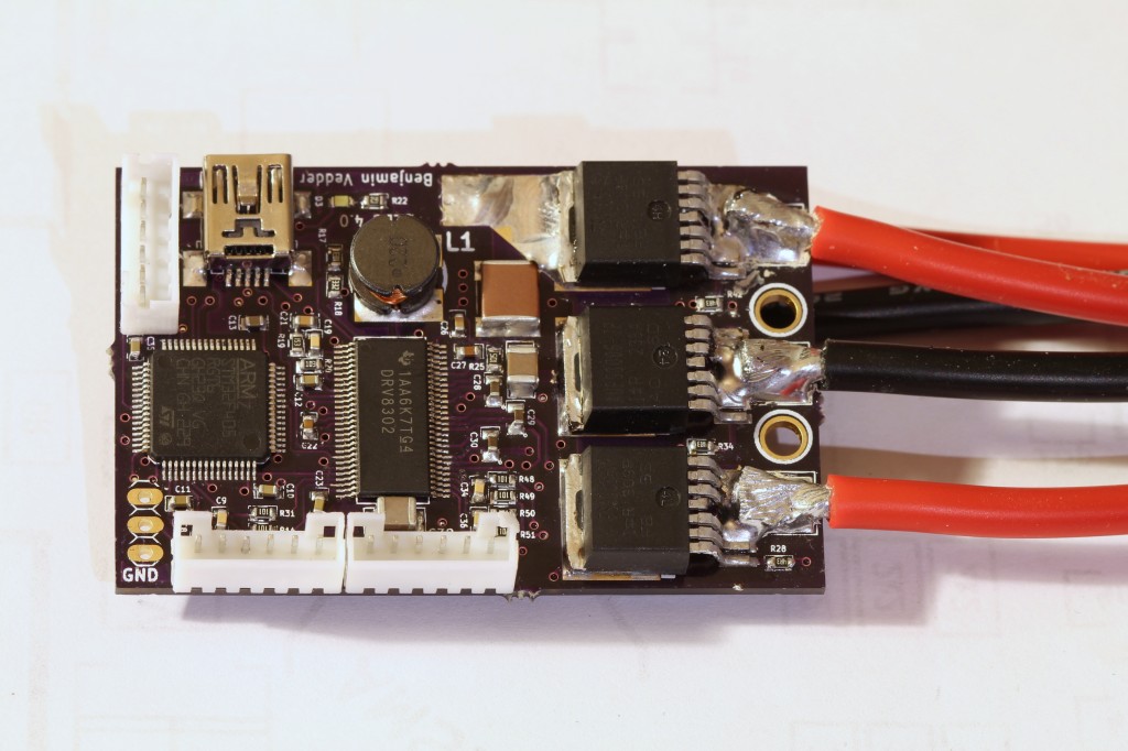
This is a photo of the front of the assembled PCB (please ignore the soldering quality…):

Front

Continue reading

A Contiki port for my custom cc2520+stm32f4-boards

Previously, I have designed a small circuit board with a cc2520 rf-tranceiver and a stm32f4 microcontroller (see this post). After porting the driver for the cc2520 to ChibiOS for a few tests, I decided to port Contiki to support this platform as well. As this is the first time that I work with Contiki, uipv6 and 6LoWPAN, this was quite a challenge for me. Nevertheless, I managed to make the following features work:

  • The cc2520 radio
  • The RPL border router using the USB connector
  • RIME
  • IPv6
  • LEDs
  • printf for debugging
  • Many applications, such as the webserver, telnet, udp
  • I made a driver for ws2811 LEDs that uses DMA and a timer

In this post, I will describe what the essential steps were to port Contiki to this board and how to use my port. I have uploaded the Contiki port together with a few example applications to github. You can download it here.

Continue reading

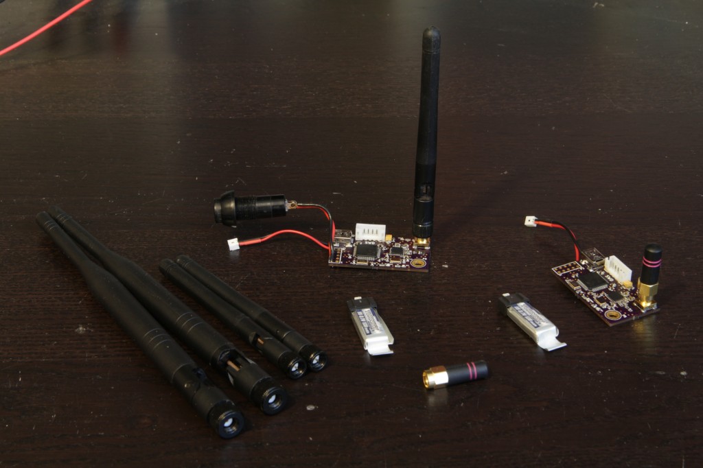
CC2520 and STM32 RF boards

I have made a small PCB with an STM32F4 microcontroller and a TI CC2520 radio transceiver. There are many mote modules available already, but I wanted one optimized for performance as opposed to power consumption. I also wanted to try making a PCB with some RF-parts since I haven’t done that before.

These are the 2-layer PCBs ordered from OSHPark:

RF_All

Continue reading

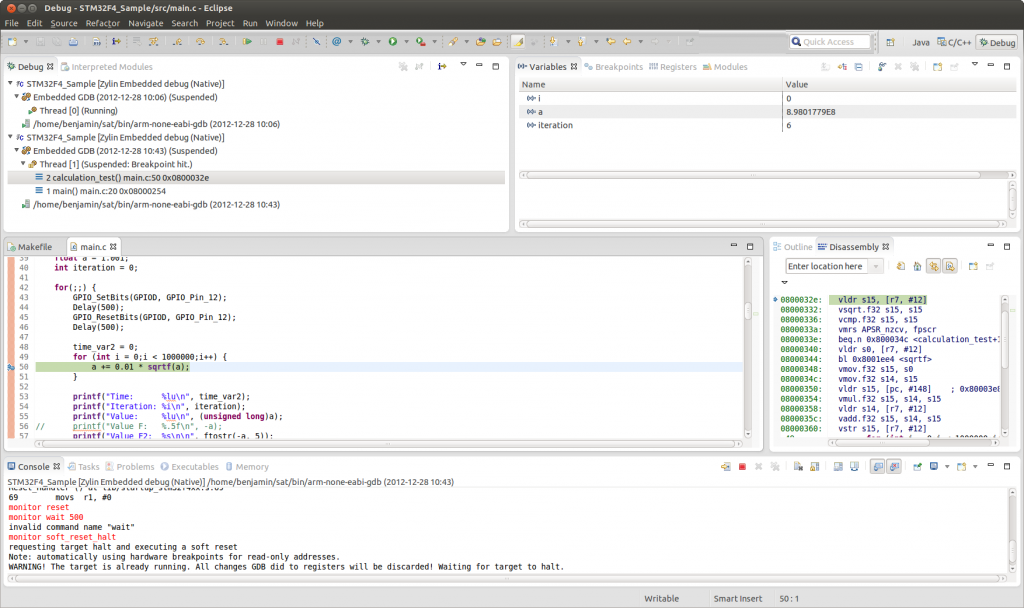
Debugging the STM32F4 using openocd, gdb and Eclipse

About

This article will describe how to debug the STM32F4 microcontroller using the zylin eclipse plugin. The following setup will be used:

  • STM32F4 discovery board
  • The built-in SWD programmer/debugger on the discovery board
  • Toolchain and example program from this tutorial (I have updated the build script for debugging to work, so if you have followed the tutorial before you may have to download and run the summon-arm script again)

The result will look something like this:

Debug_View

You can:

  • Set hardware breakpoints
  • See variable values when hitting the breakpoints
  • Change variables, then continue
  • Many other things…

Continue reading

USB-Serial on STM32F4

About

Based on this, I have written a small program for the STM32F4 Discovery that uses the USB-CDC class to show up as an virtual serial port. I’m using the USB stack provided by ST, however, there is also another project that uses libopencm3 that can be found here. I have routed the write system call to use this port, so the stdio printf function will print directly to this serial port.

How to use it

If you don’t have the necessary toolchain to build and upload programs to the STM32F4, you can have a look at this post. Otherwise, the following steps should be sufficient:

  1. Download the source code complete with all libraries and makefiles here.
  2. Unpack the program and run make from its root directory. The binary file that can be uploaded should appear in the build directory.
  3. Upload the program to the STM32F4 discovery (again, this post explains how) and plug in a micro-USB cable to the port next to the audio jack.
  4. The serial port should show up as /dev/ttyACM0 on most GNU/Linux distributions, such as Ubuntu.
  5. Start a serial port terminal, such as gtkterm (sudo apt-get install gtkterm on Debian/Ubuntu), and open ttyACM0. The baudrate does not matter as it currently is ignored by the program (see usbd_cdc_vcp.c).

The current program runs some floating point operations and prints the elapsed time on the USB-CDC serial port. The float parameters in the makefile can be changed to see how the FPU affects the speed (and there is a lot of difference). Remember to run clean after changing the float parameters, as the object files are not compatible between hardfloat and softfloat builds.

Play MP3 on the STM32F4 Discovery

Update: I also have a project that plays mp3 from an USB memory stick with a fat32 file system here.

About

I have written a simple program for the STM32F4 Discovery board that plays a short mp3 file from flash memory. For the decoding, the fixed point version of the Helix mp3 decoder is used. The audio output driver is the one used for the Peridiummmm demo, modified to use the peripheral library provided by ST.

The audio driver has two DMA buffers and a callback function that asks a user-provided function to fill one buffer with audio data when it runs out, while the other DMA buffer is streamed to the audio CODEC. This user function decodes one MP3 frame and forwards the raw audio samples to the audio driver. As this is interrupt driven, the main function can still be used for other things.

How to build and use it

If you don’t have the necessary toolchain to build and upload programs to the STM32F4, you can have a look at this post. Otherwise, the following steps should be enough to test it:

  1. Download the complete source code and makefiles here.
  2. Unpack the program and run make from its root directory. The binary file that can be uploaded should appear in the build directory.
  3. Upload the program to the STM32F4 discovery (again, this post explains how) and plug in headphones or speakers to the audio jack.
  4. You should hear some music! You can change the volume between two discrete steps by pressing the user button on the discovery board.

That’s it! It should be quite easy to modify the code to play mp3s from, for instance, an external SD card.

Use your own MP3 file

The the mp3_data[] in src/mp3_data.c is just the raw data of a normal mp3 file. I used this perl script to convert the mp3 file to a c array. After you unzip the perl script, you can use it like this:

chmod +x bin2hex
./bin2hex MP3FILE.mp3 1 > mp3_data.c

Where MP3FILE.mp3 should be replaced with the mp3 file you want to convert.

Remember that the mp3 file has to be small enough to fit on flash memory of the STM32F4. You can use Audacity to trim/re-encode mp3 files. You should also clear the ID3 tag if possible, as this saves space. As it is now, stereo files with 44.1 KHz sample rate (and any bitrate, even VBR) can be played. When the number of channels or the sample rate differs, the playback speed will become incorrect. This can of course be fixed easily, but I wanted to keep this example as simple as possible.

On Ubuntu, you can install audacity with:

sudo apt-get install audacity

Get started with the STM32F4 on Ubuntu Linux

Updated 2014-04-03

Introduction

This tutorial describes how to set up a complete and free toolchain for STM32F4xx microcontrollers, including how to use hardware floating point support. It is mostly aimed towards beginners with ARM microcontrollers, however, experienced developers could probably find something useful here as well. It is assumed that the reader is a bit familiar with the C programming language and the Bash terminal.

At the end of this tutorial, the reader should be able to build and upload programs to the STM32F4** using the STLinkV2 interface (such as the one found on the STM32F4 Discovery board). This is done using Ubuntu Linux in this tutorial, however, the instructions should be general enough to make this work on any Debian-based GNU/Linux distribution.

The following hardware/software will be used:

Continue reading