One of the major challenges when working on my custom open source ESC was to get good startup torque and low-speed performance with sensorless motors. This challenge has been addressed in several places around the net:
- Here is one article where Team Novak explain why sensored systems are superior to sensorless systems: http://teamnovak.com/tech_info/view_article/24
- This article about electric scooters has some information about that topic too: http://www.instructables.com/id/The-New-and-Improved-Brushless-Electric-Scooter-Po/step4/Controlling-the-Outrunner-Sensorless-or-Sensored/
- The metroboard has modified motors with hall sensors: http://metro-board.com/brushless-outrunner-motor-testing/
- The marbel electric skateboard also uses hall sensors: http://howtomakeanelectricskateboard.wordpress.com/2014/06/22/marbel-kickstarter/
- Here is a video of an electric longboard with a standard sensorless hobby ESC. There are obvious startup and low-speed issues: http://www.youtube.com/watch?v=SNt70MdUh0Q
Techniques I used
In order to get a smooth and quick startup without sensors I used several tricks, namely:
- There are no hardware low-pass filters that introduce phase delay. Such filters can be avoided because the ADC samples are synchronized to the PWM timer and adjusted dynamically every time the duty cycle or switching frequency is changed.
- After a zero crossing, the area under the voltage is integrated until a threshold for commutation based on the motor parameters. This integration is robust agaist acceleration and provides good SNR since an integrator is a low-pass filter.
- There is a parameter that defines the voltage coupling between the windings when measuring the back-emf. This make a huge difference when running at low speeds with low duty cycle. This compensation has a RPM dependence though, which is something I tried to avoid where possible because the RPM estimation has a delay and thus causes problems during acceleration.
- To get better voltage samples, the switching frequency is adaptive and proportional to the duty cycle. This is because the back-EMF only can be sampled during the ON-time of the PWM cycle and low duty cycles have short ON time. Since the motor is running slowly on low duty cycles, sampling and switching does not have to be as fast to keep up with the motor which makes this less of a problem. Lower switching frequency also decreases switching losses, which is a positive side-effect.
- When the motor is un-driven, the back-emf on all phases is analysed to track the position, direction and speed of the motor. So when the motor is already spinning, the algorithm will begin in the exact state of the motor (position, duty-cycle, direction).
- I have also used some hack-ish conditions based on trial and error to improve the startup.
- Closed loop operation is used from the first commutation, since the measured values are clean enough when using these techniques.
This is a video where I demonstrate how this works on a scorpion outrunner and an electric longboard:
Some examples with plots
** Note that all the plots show the voltages samples captured by the motor controller, which are synchronized to the PWM timer. It would look different on an oscilloscope since the switching distorts the signal. **
This is what the phase voltage for a typical startup sequence looks like, where the duty cycle is set to 5%:
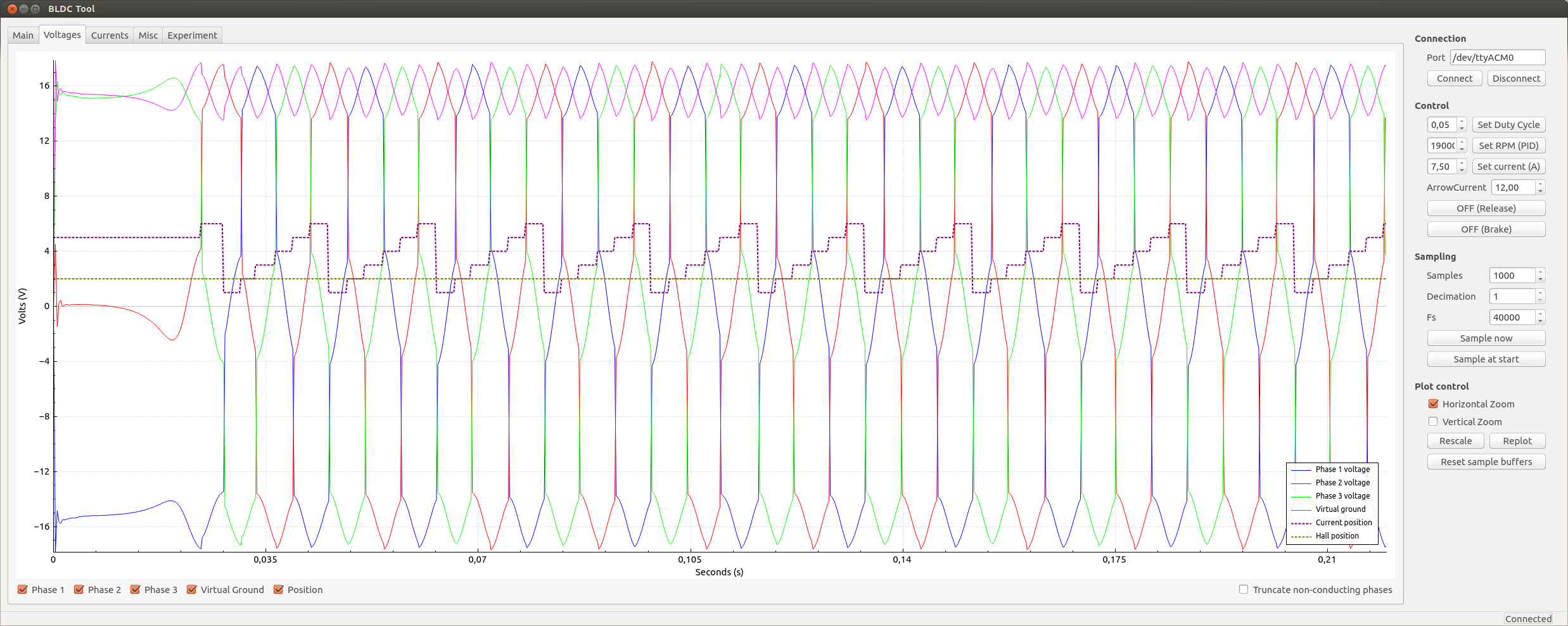
Even though the duty cycle is only 5%, the waveform is clean. This is because the switching frequency is low at this speed and the on-time is long enough to get good samples. The first commutation is a bit off at first since the motor is not perfectly aligned, but the second commutation already looks perfect.