Updated: 2016-01-22
The VESC has several extra ports and much extra computational power, so it can be used to run custom user code in addition to controlling a motor. This is convenient when there are space constraints and it is also the best way to implement real-time control applications where timing is critical. The code of the VESC is organized in such a way that it is easy to write and maintain custom applications while keeping the code up to date without having many conflicts when pulling updates using git. In this tutorial I will demonstrate how to make a custom application that will run a motor using speed control while a button is held with a speed proportional to the voltage on the ADC_EXT pin.
Preparation
Follow the tutorial in the VESC post and make sure that you can build and upload the firmware. When you can do that, you should be able to write and upload custom applications.
Connecting everything
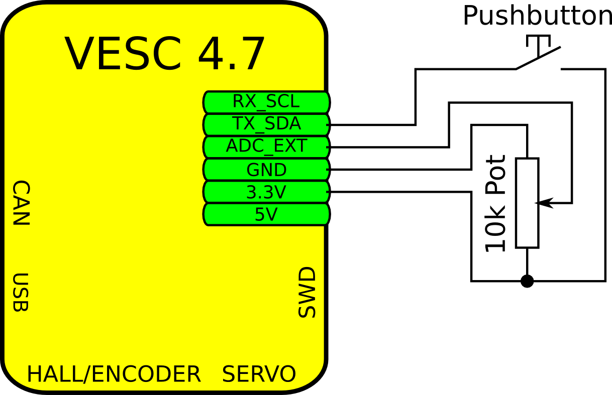
This is the example that I’m going to use in this post. When the pushbutton is held down, the VESC will run the connected motor in a speed control loop with a speed proportional to the position of the potentiometer between 0 and 10k ERPM.
Create the custom application
Download the latest firmware from using git
mkdir BLDC
cd BLDC
git clone https://github.com/vedderb/bldc.git bldc-firmware
cd bldc-firmware
In the applications directory, create a file called app_example.c and put in the following content. This is your custom application that you can edit
#include "ch.h" // ChibiOS #include "hal.h" // ChibiOS HAL #include "mc_interface.h" // Motor control functions #include "hw.h" // Pin mapping on this hardware #include "timeout.h" // To reset the timeout // Example thread static THD_FUNCTION(example_thread, arg); static THD_WORKING_AREA(example_thread_wa, 2048); // 2kb stack for this thread void app_example_init(void) { // Set the UART TX pin as an input with pulldown palSetPadMode(HW_UART_TX_PORT, HW_UART_TX_PIN, PAL_MODE_INPUT_PULLDOWN); // Start the example thread chThdCreateStatic(example_thread_wa, sizeof(example_thread_wa), NORMALPRIO, example_thread, NULL); } static THD_FUNCTION(example_thread, arg) { (void)arg; chRegSetThreadName("APP_EXAMPLE"); for(;;) { // Read the pot value and scale it to a number between 0 and 1 (see hw_46.h) float pot = (float)ADC_Value[ADC_IND_EXT]; pot /= 4095.0; if (palReadPad(HW_UART_TX_PORT, HW_UART_TX_PIN)) { // If the button is pressed, run the motor with speed control // proportional to the POT position with a speed between 0 ERPM // and 10000 ERPM mc_interface_set_pid_speed(pot * 10000.0); } else { // If the button is not pressed, release the motor mc_interface_release_motor(); } // Run this loop at 500Hz chThdSleepMilliseconds(2); // Reset the timeout timeout_reset(); } } |
Open applications.mk and add your example application to the end of APPSRC
APPSRC =	applications/app.c \
		applications/app_ppm.c \
		applications/app_adc.c \
		applications/app_sten.c \
		applications/app_uartcomm.c \
		applications/app_nunchuk.c \
		applications/app_example.c
next open app.h and add a definition for your example application under Custom apps
// Custom apps void app_gurgalof_init(void); void app_sten_init(void); void app_example_init(void); // Your application |
now open app.c and add your app under the APP_CUSTOM case in the init function:
void app_init(app_configuration *conf) { app_set_configuration(conf); switch (appconf.app_to_use) { case APP_PPM: app_ppm_start(); break; case APP_ADC: app_adc_start(); break; case APP_UART: hw_stop_i2c(); app_uartcomm_start(); break; case APP_PPM_UART: hw_stop_i2c(); app_ppm_start(); app_uartcomm_start(); break; case APP_ADC_UART: hw_stop_i2c(); app_adc_start(); app_uartcomm_start(); break; case APP_NUNCHUK: app_nunchuk_start(); break; case APP_NRF: nrf_driver_init(); break; case APP_CUSTOM: #ifdef USE_APP_STEN hw_stop_i2c(); app_sten_init(); #endif app_example_init(); // Your example application break; default: break; } } |
After this you are done editing the source code, so connect a programmer to the VESC. Go to the terminal in the bldc-firmware directory and type make upload to build and upload the firmware.
make upload
Alternatively, you can just type make and upload the the firmware using BLDC Tool and the bootloader. The .bin file for the firmware will be created in the build directory under bldc-firmware.
Using your custom application
Configure the VESC as described in my other post as usual. In the app configuration, select custom user application
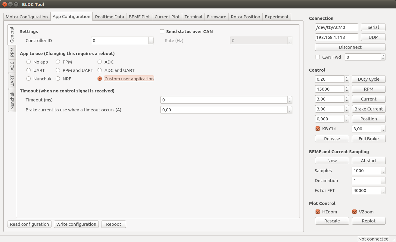
and write the configuration. The next time the VESC boots, your custom example application will be loaded. Not too difficult, right?
Some tips
- Have a look at the other applications for some inspiration.
- mcpwm.h has all motor control functions and measurements that you can use.
- The pin macros for the UART TX pin in this example are found in hwconf/hw_46.h. The ADC macros are also found there.
- To print text for debugging in the BLDC Tool terminal, include commands.h and use the commands_printf function like the normal printf in C.
- Include can.h and use the functions there to communicate with other VESCs over CAN bus. It is fairly easy and straight forward.
- Have a look at the ChibiOS documentation which is very good. The testhal directory for this MCU has some good example applications that you can have a look at. Just be careful to not use drivers that are used by the VESC already, such as ADC. To read ADC values, use the macros and indexes found in hw_46.h that will use the existing implementation.
- Eclipse is good for editing C source code. Just create a makefile project in eclipse and base it on the bldc-firmware directory. I will update this post or write a new one with how to make the indexing work in eclipse for C makefile projects, which is very useful.
Updates
- 2016-01-22: Changed mcpwm to mc_interface for the FOC update.
Pingback: VESC – Open Source ESC | Benjamin's robotics
Dear all,
I followed the example for writing a custom application for the VESC.
I could follow all the description, including setting up the motor configuration (I run a small 22mm diameter 875kv motor), and finally start the motor with the button and change the speed according to the potentiometer position. All this works fine, but about one second after the moment when I push the “disconnect”-button or remove the USB cable from the VESC the motor starts to run poorly. The other way round after reconnecting the motor to the BLDC-Tool and the “connected” is shown in the lower right corner the motor runs fine again.
Does anybody has an idea what is the problem? Could it be that I use the wrong BLDC-Tool version? I found the “disconnect” button on the last screen shot of the example looks diferent and an “UDP” button is added.
Max
Hi Max,
This is because you need to reset the timeout, which by default will try to stop the motor after one second. I forgot to put that in the example code at first, but it is there now.
/Benjamin
Can you estimate the minimum STM32 chip FLASH/RAM/MHz needed to run a minimal custom app? Also this F405 chip has 3x fast A/D. Is that needed for the BEMF integration? I want to see if this code can run on something like an STM32F103 family. What do you think?
Thanks,
Chris
Porting the code to a f103 would be a lot of work and many features have to be removed. All floating point calculations at high rate have to be converted to fixed point. The possibility to use FOC will be limited as well. I don’t recommend using a slower mcu.
Dear Benjamin,
thanks for the modified example code. Now, after including the timeout, everithing works fine with my small 22mm diameter 875kv motor.
Unfortunately I’ve problems to run my custom made motor with the VESC settings.
It is a inrunner with 160mm air gap, 14 pole pairs, 24 slots and a single layer Y winding scheme (only every second tooth is wound). It is a heavy rotor with a huge inertia and the 140mm ball bearing filled with sticky grease, what makes a lot of friction.
After pressing the “start detection” rotor movement is only observed when “current” is ~1,5A, “Min-ERPM” is ~100 and “Low Duty” is ~0,15. The rotor makes about 15 commutations (about 3/4 of a turn). The commutations are not fluently but really stepwise with a kind of back swinging after each step. In the second half of the detection routine the rotor tries to rotate but the power seems to be too low (“Real time data” show a duty cycle of 5% what seems to be too low).
Finding “integration limit” and “BEMF-Coupling” by try and error was not successfull and running the motor from the key board or any how else is not possible.
I’ve the suspicion that a fast acceleration, as might be needed in the detection mode, is not possible with this “heavy and lot of friction” motor. Furthermore, even when the right “integration limit” and “BEMF-Coupling” setting would be found, the initial auto commutation/acceleration is too fast.
Do you think changing some parameters (in the C-code) could be helpful? Which one?
I tried to use hall sensors, but the best practise is not clear to me (What I’ve to insert in the “Motor settings”; what I’ve to look for in the “BEMF plot”) .
Is it possible to get reasonable BEMF-plots when the motor can’t rotate by itself?
Sorry for this lot of questiones, but maybe someone else is also faced with similar problems.
Thanks in advance
Maxi
Hi Maxi,
I have a motor with a similar problem. I haven’t found a good way to make the detection work other than trial and error and looking at the back emf shape when commutations are made. A good value to start with the integrator limit is 282000 / (motor_kv * poles) (e.g. 282000 / (168 * 14) for my 14 pole 168kv outrunner). For the coupling you can use something like 500.
To make it start a motor with more inertia you can decrease the min RPM values.
/Benjamin
HI Benjamin
I an writing a custom application with your VESC and I have a problem.
I want the motor to free run when I execute mcpwm_release_motor().
But it stops abruptly just as if there is a brake.
I tried to turn the wheels with my hand but it feels as if the brake is on and doesn’t free run.
With your applications such as PPM the motor seems to free run fine when no throttle is given.
Could you help me with this problem?
By the way I love your VESC.
Sincerely,
Kim Hoon.
Hi Kim,
That should work. Can I see your code?
Please post updates if you went private, it would be nice to know what the problem was 🙂
I have a question about generating highest torque for a high inertia load. I am trying to determine which parameter most affects 0 RPM startup torque. So far, I can easily see how Startup Boost in the Advanced settings can affect torque after some initial motor spin. However, I am wondering if ERPM in the Sensorless tab or Current in the Right hand Control box will be most effective. I am running Current mode with a sensorless 5060 motor.
Basically, I am not fully understanding the ERPM parameter. Does this equate to something that I can use as a formula point. I know what I am trying to spin, so other than trial and error, how do I set it?
Thanks,
Hi Benjamin,
As I explained before, we are developing brushless camera gimbals. DRV8302 is too big and expensive for small camera gimbal drivers. In our design, we want to use LMV358 to amplify current signal , FDC6330L and FDC637N mosfets to drive the small brushless motor. And as I asked before, is it possible to port the code to run on the 48-pin STM32f302 ? What do you think ? If possible, please give me your email address, we’d like you to take a look at our schematics, thank you for your help !
Thanks
Hi Benjamin,
We are developing brushless camera gimbals, and I ran across your video clip showing great position control with VESC,
https://www.youtube.com/watch?v=qqNOx57f2OU
Very impressive. I assume that it is done with a motor with encoder, however, in our case, we need absolute angular position so instead of encoder we chose a GMR-Based Angle Sensor — TLE5012B.
I suppose we need to modify your software. I appreciate your feedback as to where and how to modify your software to use angle sensor to drive brushless camera gimbals.
Thanks a lot.
Li
I’m actually working on implementing support for the AS5047P absolute angular sensor, which is very similar to the one you linked to. Maybe you can use that one.
That’s good news. When will you be able to release support for absolute angle sensor ?
Actually we just bought a sensored motor equipped with AS5048, should be compatible with AS5047P. But Infineon’s TLE5012B costs much less, and also provides 14-bit output.
Currently I don’t have so much time, but I will try to finish it within next week or so.
I had a quick look at the AS5048, and I think it should work with the same code. The TLE5012B looks different though. One disadvantage with the TLE5120B is that it only work up to 10K RPM, while the AS5047P goes to 28K RPM.
Hi Benjamin,
That’s great news, please post when you complete your work with the AS5047P sensor.
Got another question for you. While STM32F405 is great with tons of features, we hope to use STM32F103 or F105 as it is much smaller and cheaper. I am aware of its limited flash and ram size. do you think if it is possible to port your code to F103 or F105 ?
hi Benjamin,
We understand that STM32F103 is not powerful enough without FPU, but how about STM32F302 which has smaller 48-pin footprint with floating point unit, however running at lower clock. Could you please take a quick look and see if it is feasible to port your code to it ?
Thanks a lot
Li
Hi Benjamin,
As I explained before, we are developing brushless camera gimbals. DRV8302 is too big and expensive for small camera gimbal drivers. In our design, we want to use LMV358 to amplify current signal , FDC6330L and FDC637N mosfets to drive the small brushless motor. And as I asked before, is it possible to port the code to run on the 48-pin STM32f302 ? What do you think ? If possible, please give me your email address, we’d like you to take a look at our schematics, thank you for your help !
Porting the code to a different microcontroller is not easy. The f103 is not powerful enough for sure, especially since it has no FPU. The f302 should have enough computational power if the switching frequency isn’t too high, but porting the code is still a lot of work. Working full time I could probably get most things running in a week or so, but I have much less than full time available and so many other projects, so I don’t think I can do something like this any time soon.
The AS5047 support is now implemented in FW2.17 and can be configured in BLDC Tool. To use it, remove the filters on the sensor port and connect:
SCK -> HALL 1
MISO -> HALL 2
MOSI -> VCC
CS -> HALL 3
Hi Benjamin,
I want to use your foc implementation to control the bldc sensored hub motor so i need gyro/accelerometer readings via your i2c port.
Is it possible to use this controller as an unicycle mainboard?
Hello,
I am looking to control the motor via bluetooth. how can i do that?
thank you
Dear Benjamin,
I am studying the BLDC project these days and now I have a question about the servo decoder part.
As far as I know that you use the ICU Driver to acquire the PPM signal. But what makes me confused is that the values about the PPM signal displayed in configuration GUI(returned by servodec_get_servo() and servodec_get_last_pulse_len()) are always shaking(my ppm signal generator is ok and shaking between1%–2%). Have you noticed this problem? Is it OK? Or is there anything wrong with the ICU Driver ? I just don’t want to use the filter to solve this problem, and is there any other way better?
I am just confused about it these days! I am looking forward to your reply.
Hi Benjamin,
I am testing VESC with ppm input, which runs great in general. However, I noticed that pulse width is moving around quite a bit even though the input pulse width is stable. I noticed that the pulse width is read by the following callback
static void icuwidthcb(ICUDriver *icup) {
last_len_received[0] = ((float)icuGetWidthX(icup) / ((float)TIMER_FREQ / 1000.0));
float len = last_len_received[0] – pulse_start;
const float len_set = (pulse_end – pulse_start);
It appears that Chibios ICU (input capture unit) capture function icuGetWidthX() returns unstable value. I am not sure if this function utilizes hardware timer capture capability, which should be very precise.
Have you noticed this problem before ? do you know if there’s anyway we can improve pulse width reading ?
Is there enough power to run two motors off one STM?
Hi Benjamin,
As always thank you very much for sharing your amazing work !
We need to run with duty cycle no reverse mode for our multirotor UAV project, in order to get fastest dynamic response possible. We noticed that this mode has brake turned on, perhaps as a result the motor gets hot with loss of energy efficiency. we also get squeaking sound when turning throttle up and down very fast. Sometimes on startup the motor runs in reverse direction as well.
We noticed that when run with a motor designed for FOC, the performance is very good.
my questions are:
1. how do I turn off brake in duty cycle modes ?
2. is it necessary to use only PSMS motor designed for sinusoidal control ? we tried BLDC control for our motors, without much improvement.
Thank you for your help.