Post updated 2016-01-22
About this project
I have made many updates to my custom motor controller recently and the old post is getting confusing with notes and updates, I decided to write a new post about it that hopefully is more clear, more complete and easier to follow. This might sound a bit ambitions, but my goal is to make the best ESC available. I really enjoy sharing knowledge, so I want to keep all the hardware and software open.
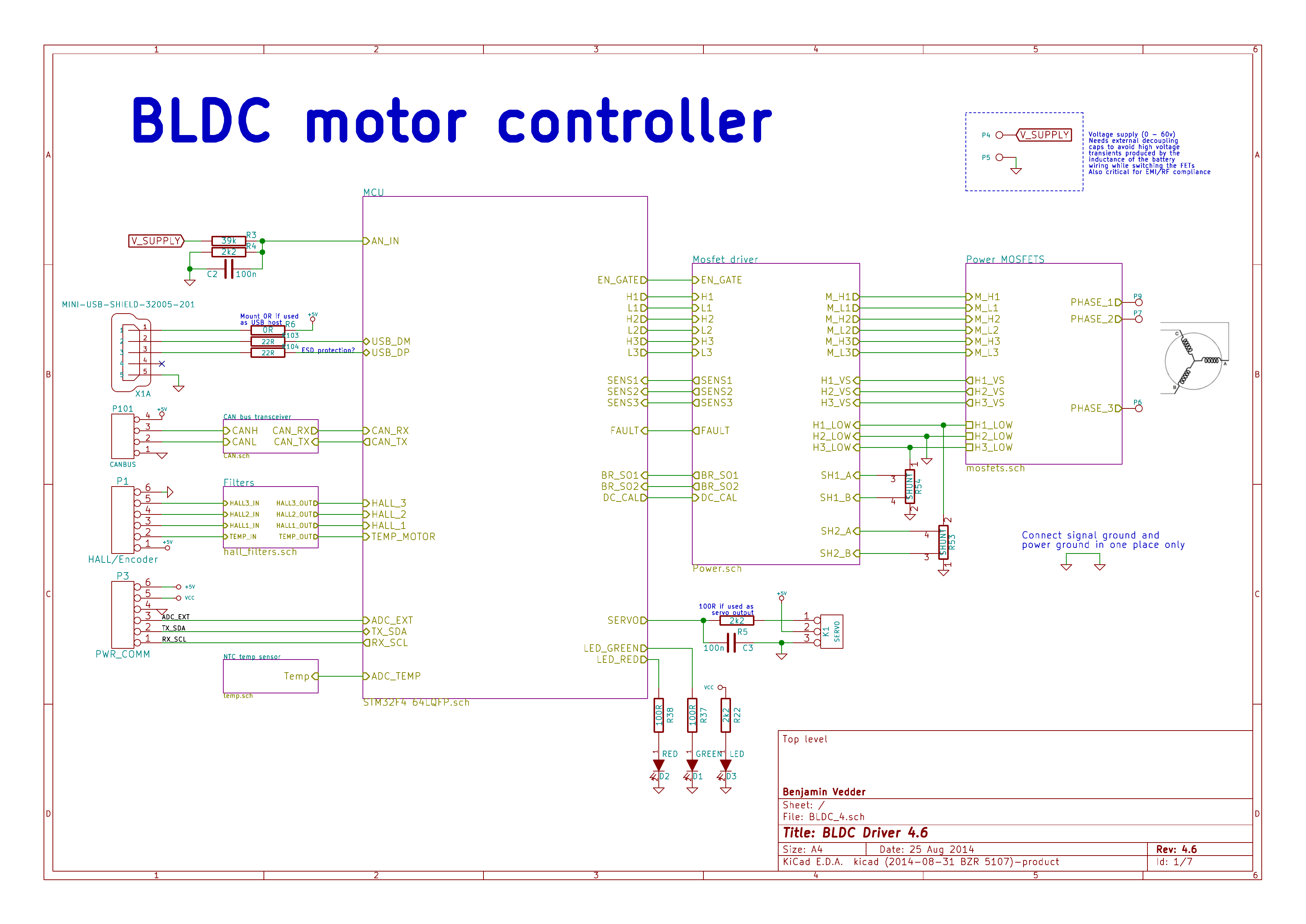
This is an overview of the schematic (download a complete PDF here):
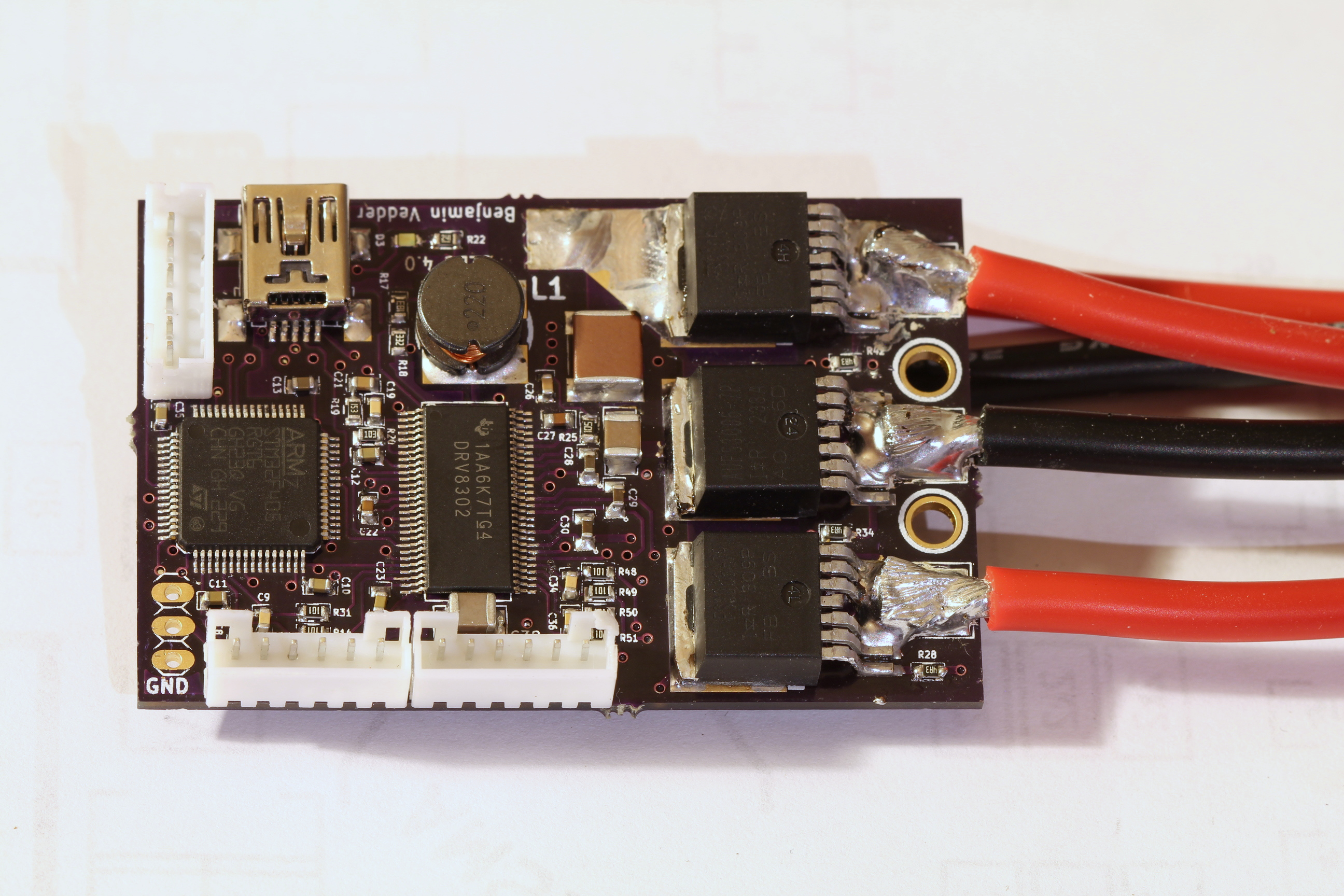
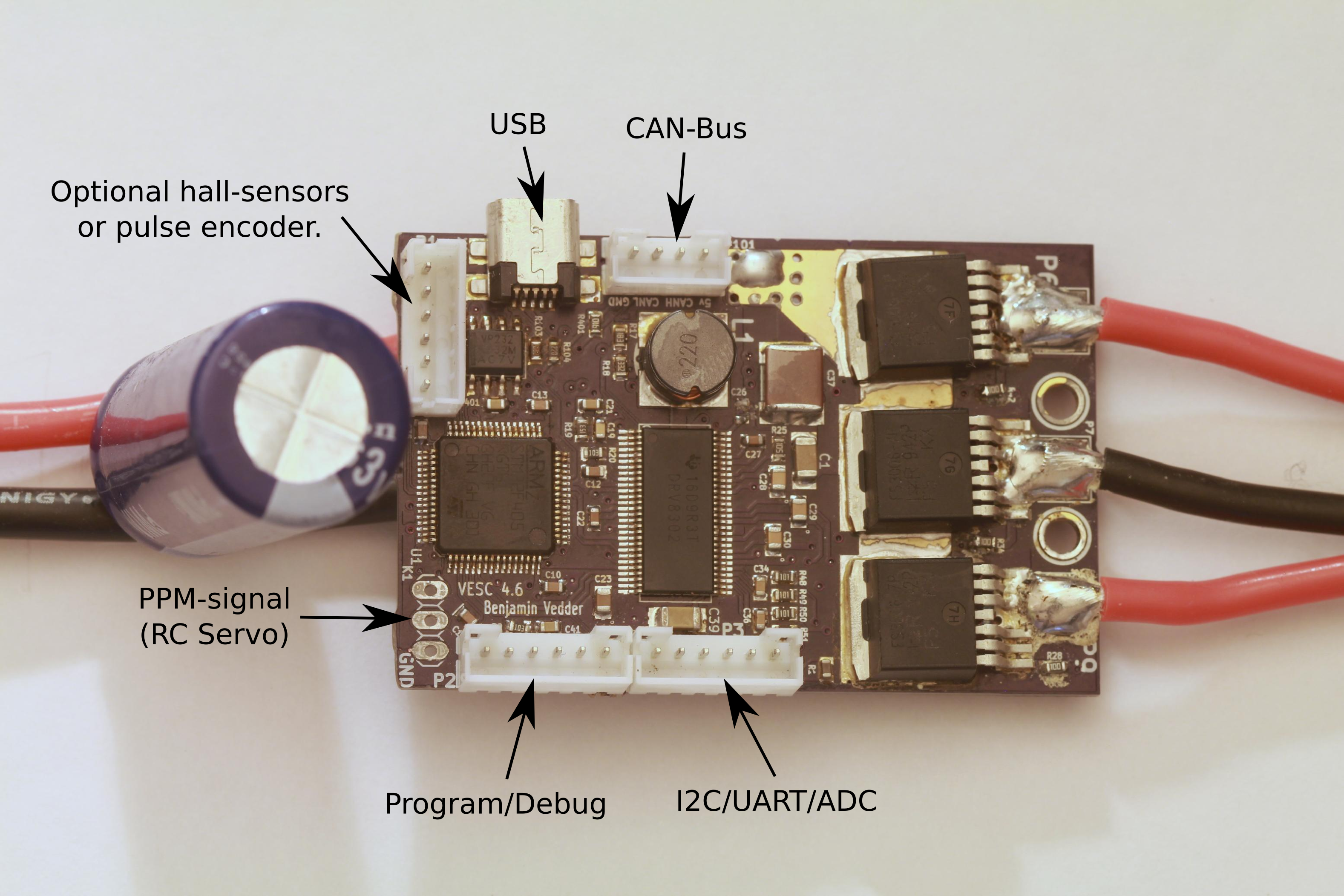
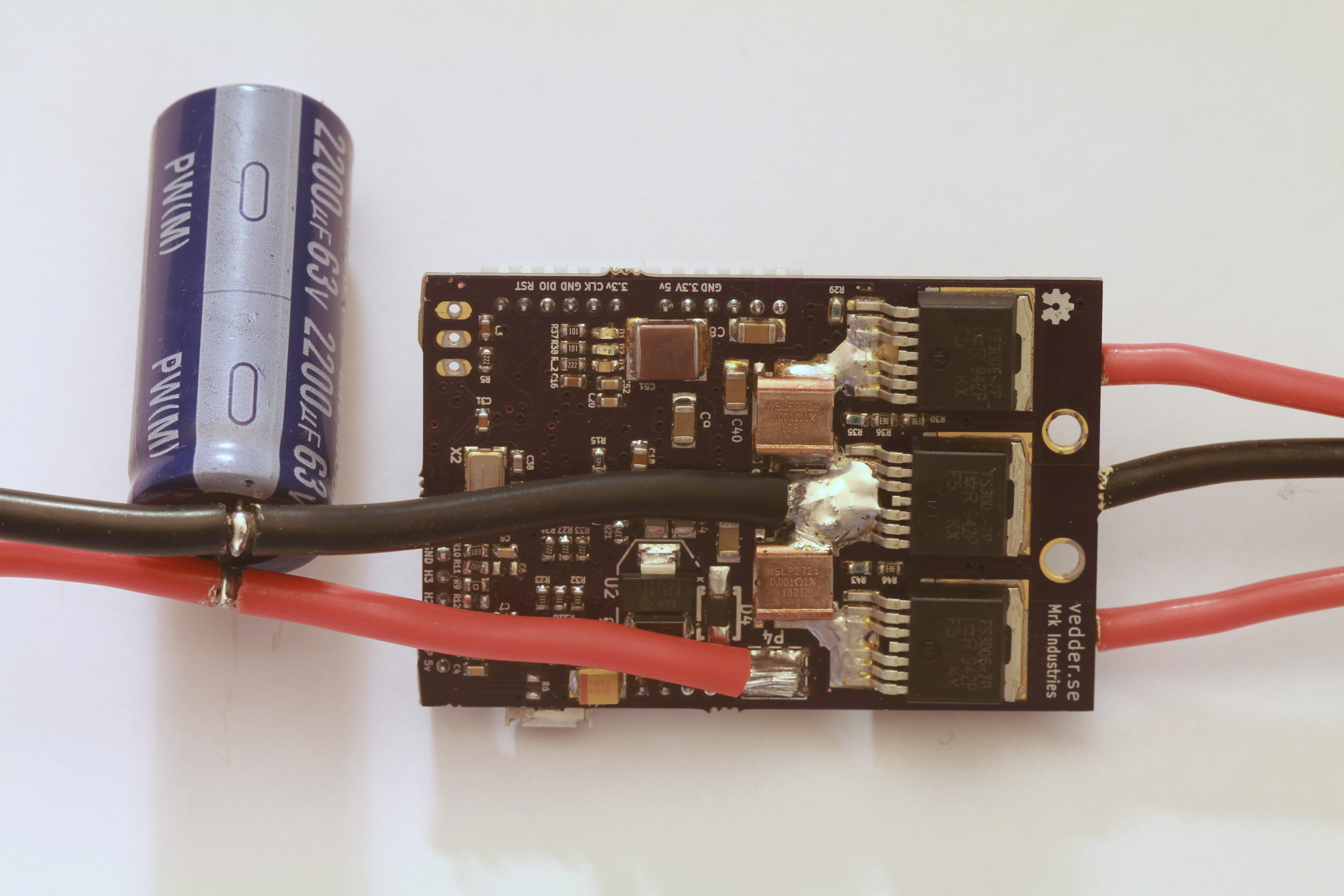
This is the front of the PCB:
The back:
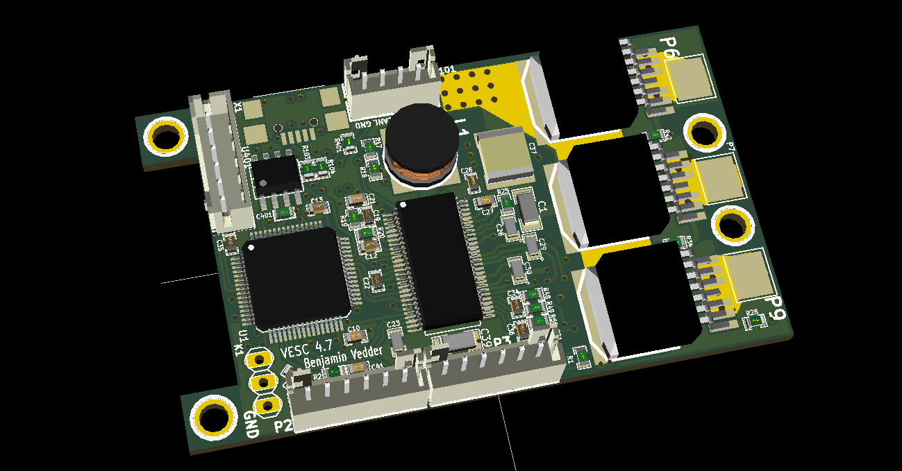
3D render from KiCad:
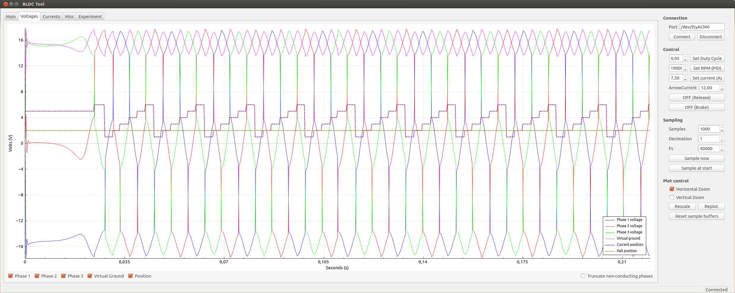
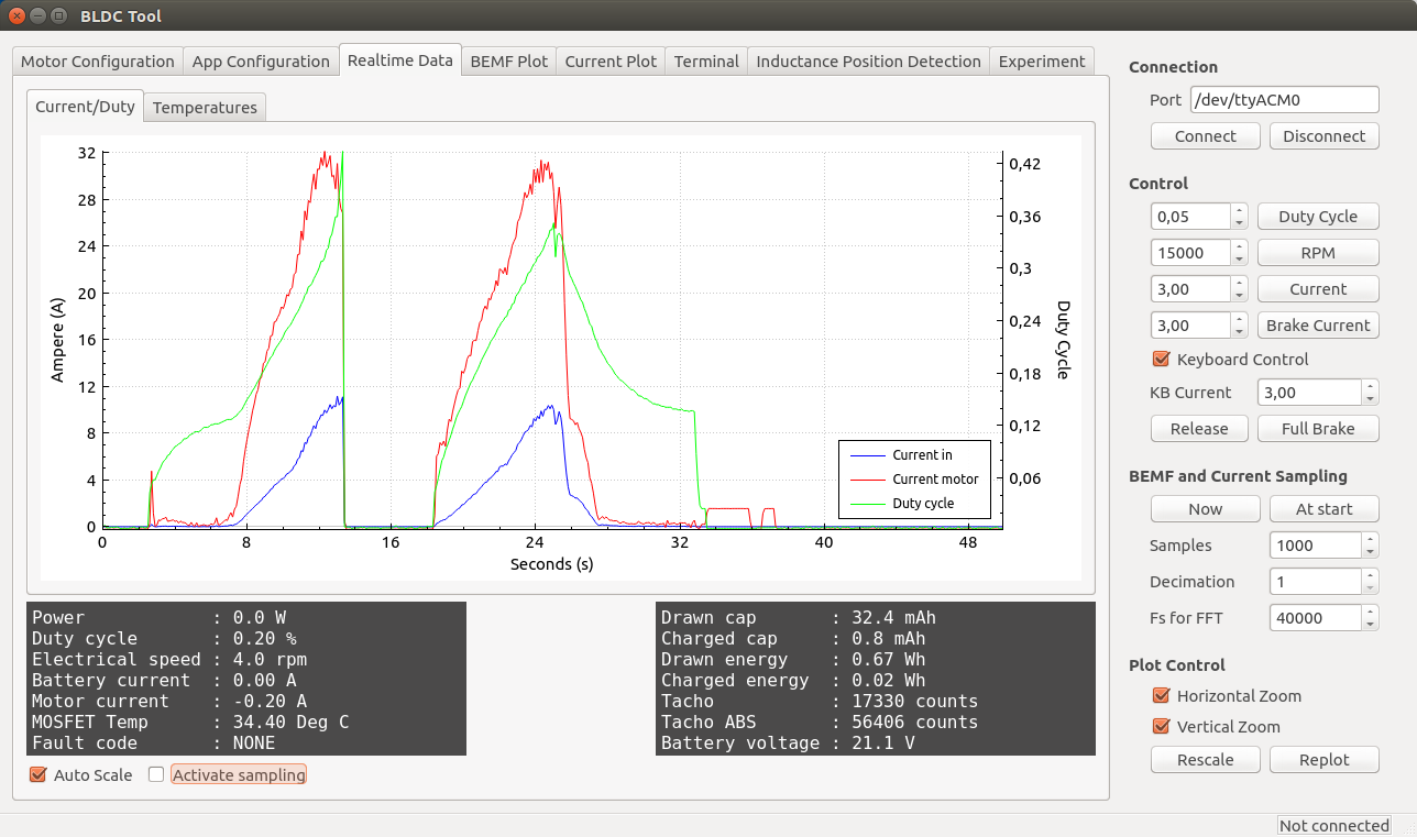
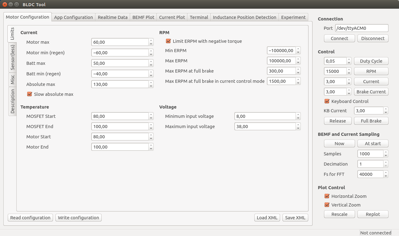
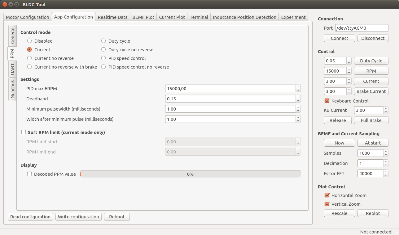
Some screenshots of the configuration GUI (BLDC Tool):
Resources
All files are on github to keep them up to date, so check these links on a regular basis:
- Hardware design
- Bill of materials
- Firmware
- Configuration GUI
- Video logger
- osx and windows builds of BLDC Tool, Video logger etc. by Jacob Bloy
Related posts
- Old post motor controller (just for reference)
- Video overlay logging
- Electric skateboard motor tutorial (KV, cells, etc.)
- Startup torque
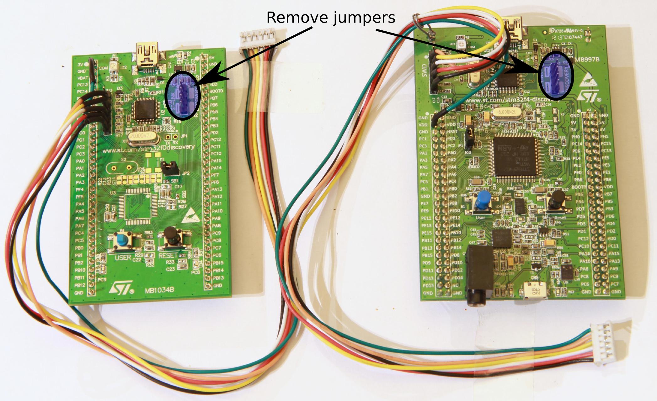
- Hardware debugging
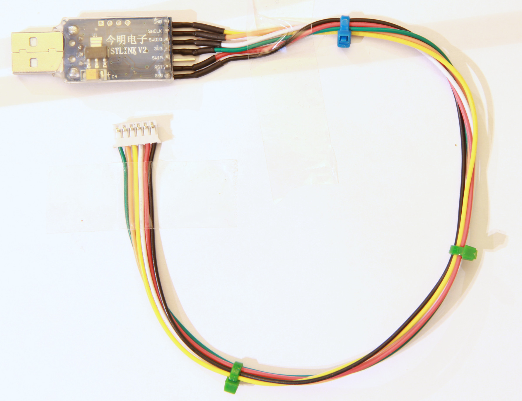
- Making a programmer
- Writing custom applications
- UART Communication
Forums
Because information about the VESC is scattered all over the internet and a lot of information is in email conversations with me, I have created a forum dedicated to the VESC here.
Live Chat
I have created an IRC channel on freenode where you can live chat with me and other users about VESC and my other projects. Feel free to join: http://webchat.freenode.net/?channels=vedder
Features
- The hardware and software is open source. Since there are plenty of CPU-resources left, the customization possibilities are almost endless.
- STM32F4 microcontroller.
- DRV8302 MOSFET driver / buck converter / current shunt amplifier.
- IRFS7530 MOEFETs (other FETs in the same package also fit).
- 5V 1A output for external electronics from the buck converter integrated on the DRV8302.
- Voltage: 8V – 60V (Safe for 3S to 12S LiPo).
- Current: Up to 240A for a couple of seconds or about 50A continuous depending on the temperature and air circulation around the PCB.
- Sensored and sensorless FOC wich auto-detection of all motor parameters is implemented since FW 2.3.
- Firmware based on ChibiOS/RT.
- PCB size: slightly less than 40mm x 60mm.
- Current and voltage measurement on all phases.
- Regenerative braking.
- DC motors are also supported.
- Sensored or sensorless operation.
- A GUI with lots of configuration parameters
- Adaptive PWM frequency to get as good ADC measurements as possible.
- RPM-based phase advance (or timing/field weakening).
- Good start-up torque in the sensorless mode (and obviously in the sensored mode as well).
- The motor is used as a tachometer, which is good for odometry on modified RC cars.
- Duty-cycle control, speed control or current control.
- Seamless 4-quadrant operation.
- Interface to control the motor: PPM signal (RC servo), analog, UART, I2C, USB or CAN-bus.
- Wireless wii nunchuk (Nyko Kama) control through the I2C port. This is convenient for electric skateboards.
- Consumed and regenerated amp-hour and watt-hour counting.
- Optional PPM signal output. Useful when e.g. controlling an RC car from a raspberry pi or an android device.
- The USB port uses the modem profile, so an Android device can be connected to the motor controller without rooting. Because of the servo output, the odometry and the extra ADC inputs (that can be used for sensors), this is perfect for modifying an RC car to be controlled from Android (or raspberry pi).
- Adjustable protection against
- Low input voltage
- High input voltage
- High motor current
- High input current
- High regenerative braking current (separate limits for the motor and the input)
- Rapid duty cycle changes (ramping)
- High RPM (separate limits for each direction).
- When the current limits are hit, a soft back-off strategy is used while the motor keeps running. If the current becomes way too high, the motor is switched off completely.
- The RPM limit also has a soft back-off strategy.
- Commutation works perfectly even when the speed of the motor changes rapidly. This is due to the fact that the magnetic flux is integrated after the zero crossing instead of adding a delay based on the previous speed.
- When the motor is rotating while the controller is off, the commutations and the direction are tracked. The duty-cycle to get the same speed is also calculated. This is to get a smooth start when the motor is already spinning.
- All of the hardware is ready for sensorless field-oriented control (FOC).
Writing the software is the remaining part. However, I’m not sure if FOC will have many benefits for low inductance high-speed motors besides running a bit quieter.Sensored and sensorless FOC is fully implemented since FW 2.3.