================= IMPORTANT UPDATE =================
I have written a new post about my open ESC on this page and also updated the hardware significantly. If you haven’t built it yet and if you are planning to order parts for it, please refer to that page. I will only leave this page for reference in case you have built it before I wrote the new post and updated the hardware. Also, If you have built the ESC before, the tutorial and software on the new page also applies to the old hardware.
=====================================================
Updated 2014-12-08
For about three years I have been working on a custom BLDC motor controller (also known as an ESC). I have spent hundreds of hours on writing code and I have made many minor and four major revisions of the printed circuit board (PCB). Now I finally have something that I can publish. The code can still be cleaned up a lot, especially the latest parts that I wrote in a hurry, but I don’t want to delay the release forever.
The features of this BLDC controller are:
- The hardware and software is open source.
- A STM32F4 microcontroller.
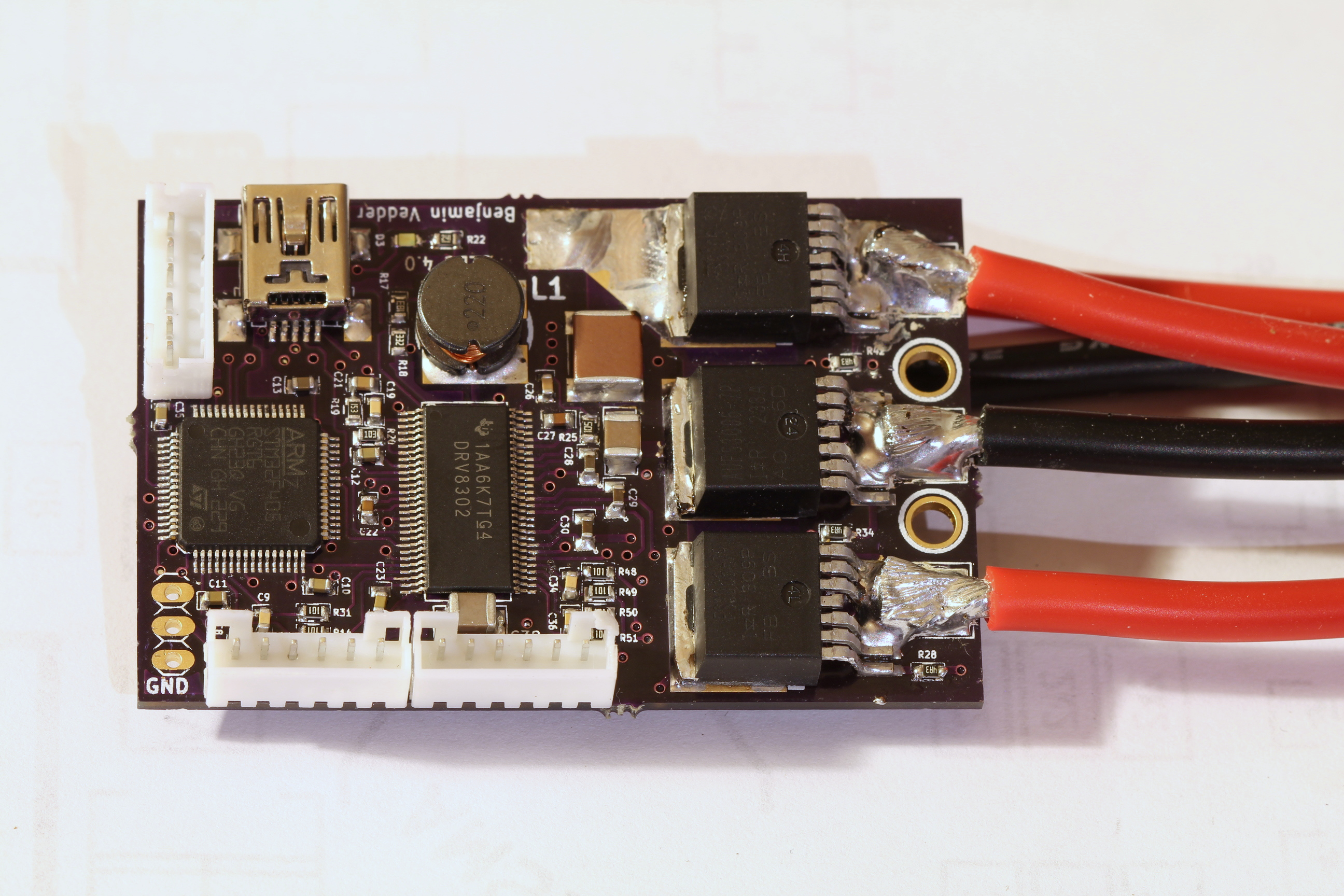
- A DRV8302 MOSFET driver / buck converter / current shunt amplifier.
- IRFS3006 MOEFETs.
- 5V 1A output for external electronics from the buck converter integrated on the DRV8302.
- Voltage: 8V – 60V.
- Current: Up to 240A for a couple of seconds or about 50A continuous depending on the cooling.
- PCB size: slightly less than 40mm x 60mm.
- Current and voltage measurement on all phases.
- Regenerative braking.
- Sensored or sensorless commutation.
- Adaptive PWM frequency to get as good ADC measurements as possible.
- RPM-based phase advance.
- Good start-up torque in the sensorless mode (and obviously in the sensored mode as well).
- The motor is used as a tachometer, which is good for odometry on modified RC cars.
- Duty-cycle control, speed control or current control.
- Seamless 4-quadrant operation.
- Interface to control the motor: servo signal, analog, UART, I2C, USB or CAN (with a transceiver). Some of these modes need a bit more code to work, but not much.
- Servo signal output. Good when e.g. controlling an RC car from a raspberry pi or an android device.
- The USB port uses the modem profile, so an Android device can be connected to the motor controller without rooting. Because of the servo output, the odometry and the extra ADC inputs (that can be used for sensors), this is perfect for modifying a RC car to be controlled from Android (or raspberry pi).
- Adjustable protection against
- Low input voltage
- High input voltage
- High motor current
- High input current
- High regenerative braking current (separate limits for the motor and the input)
- Rapid duty cycle changes (ramping)
- High RPM (separate limits for each direction).
- When the current limits are hit, a soft back-off strategy is used while the motor keeps running.
- The RPM limit also has a soft back-off strategy.
- The commutation works perfectly even when the speed of the motor changes rapidly. This is due to the fact that the magnetic flux is integrated after the zero crossing instead of adding a delay based on the previous speed.
- When the motor is rotating while the controller is off, the commutations and the direction are tracked. The duty-cycle to get the same speed is also calculated. This is to get a smooth start when the motor is already spinning.
- All of the hardware is ready for sensorless field-oriented control (FOC). Writing the software is the remaining part.
This is a photo of the front of the assembled PCB (please ignore the soldering quality…):