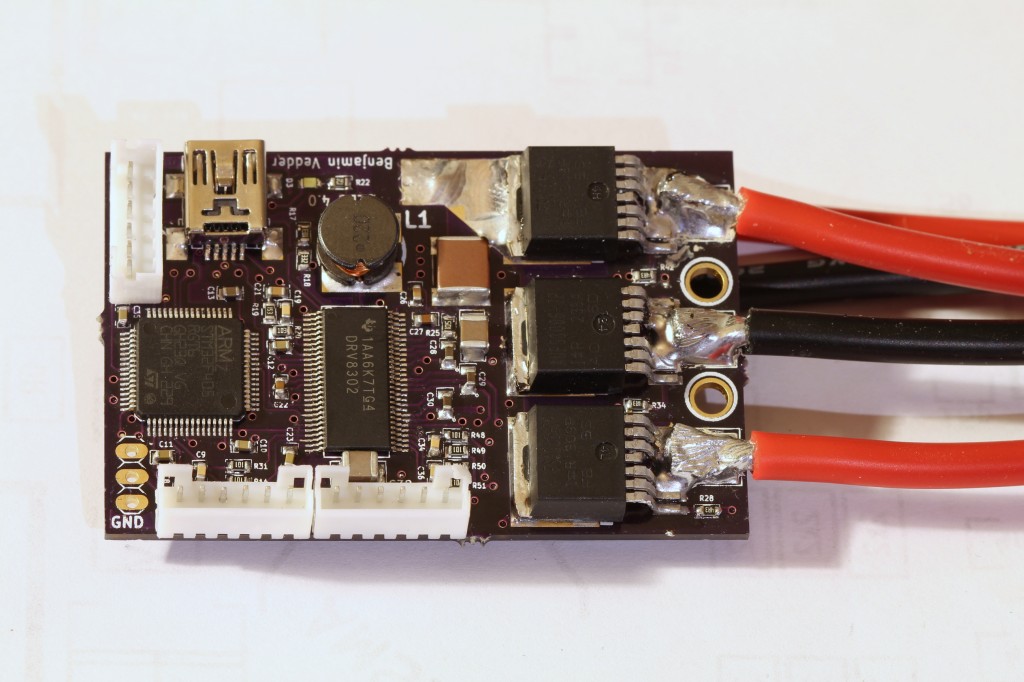
A custom BLDC motor controller (a custom ESC)

================= IMPORTANT UPDATE =================

I have written a new post about my open ESC on this page and also updated the hardware significantly. If you haven’t built it yet and if you are planning to order parts for it, please refer to that page. I will only leave this page for reference in case you have built it before I wrote the new post and updated the hardware. Also, If you have built the ESC before, the tutorial and software on the new page also applies to the old hardware.

=====================================================

Updated 2014-12-08

For about three years I have been working on a custom BLDC motor controller (also known as an ESC). I have spent hundreds of hours on writing code and I have made many minor and four major revisions of the printed circuit board (PCB). Now I finally have something that I can publish. The code can still be cleaned up a lot, especially the latest parts that I wrote in a hurry, but I don’t want to delay the release forever.

The features of this BLDC controller are:

  • The hardware and software is open source.
  • A STM32F4 microcontroller.
  • A DRV8302 MOSFET driver / buck converter / current shunt amplifier.
  • IRFS3006 MOEFETs.
  • 5V 1A output for external electronics from the buck converter integrated on the DRV8302.
  • Voltage: 8V – 60V.
  • Current: Up to 240A for a couple of seconds or about 50A continuous depending on the cooling.
  • PCB size: slightly less than 40mm x 60mm.
  • Current and voltage measurement on all phases.
  • Regenerative braking.
  • Sensored or sensorless commutation.
  • Adaptive PWM frequency to get as good ADC measurements as possible.
  • RPM-based phase advance.
  • Good start-up torque in the sensorless mode (and obviously in the sensored mode as well).
  • The motor is used as a tachometer, which is good for odometry on modified RC cars.
  • Duty-cycle control, speed control or current control.
  • Seamless 4-quadrant operation.
  • Interface to control the motor: servo signal, analog, UART, I2C, USB  or CAN (with a transceiver). Some of these modes need a bit more code to work, but not much.
  • Servo signal output. Good when e.g. controlling an RC car from a raspberry pi or an android device.
  • The USB port uses the modem profile, so an Android device can be connected to the motor controller without rooting. Because of the servo output, the odometry and the extra ADC inputs (that can be used for sensors), this is perfect for modifying a RC car to be controlled from Android (or raspberry pi).
  • Adjustable protection against
    • Low input voltage
    • High input voltage
    • High motor current
    • High input current
    • High regenerative braking current (separate limits for the motor and the input)
    • Rapid duty cycle changes (ramping)
    • High RPM (separate limits for each direction).
  • When the current limits are hit, a soft back-off strategy is used while the motor keeps running.
  • The RPM limit also has a soft back-off strategy.
  • The commutation works perfectly even when the speed of the motor changes rapidly. This is due to the fact that the magnetic flux is integrated after the zero crossing instead of adding a delay based on the previous speed.
  • When the motor is rotating while the controller is off, the commutations and the direction are tracked. The duty-cycle to get the same speed is also calculated. This is to get a smooth start when the motor is already spinning.
  • All of the hardware is ready for sensorless field-oriented control (FOC). Writing the software is the remaining part.

This is a photo of the front of the assembled PCB (please ignore the soldering quality…):

Front

Continue reading

Testing a simple sumo program using 3 proximity sensors

During RobotChallenge Sleipner was using 7 proximity sensors, but this did not work very well. The reason for that is that the sensors had 140cm ± 3% range almost regardless of the surface of the object. Most things were closer than that to the dohyo, so most of the matches were quite random.

The tests in the video below are done with only 3 sensors, but no objects are closer to the dohyo than 150cm. As it turns out this is quite enough even with a simple program. One problem is that the sensors are a bit slow, so while the robots turns at high speed small objects such as the can won’t trigger the sensors. Otherwise, the robot should abort the rotation and attack.

Considerations for the next robot

Sensors are among the biggest challenges when building sumo robots. Good sensors are really expensive and… not that good. My plan is to hopefully get some 200+ fps camera sensor and use an FPGA to approximate the position of the other robot. I’m quite familiar with Xilinx FPGAs and VHLD but I have only seen pretty slow camera sensors with a documented interface and an affordable price.

In general I would like to build the robot without spending too much money on it. Firstly because I’m a student and can’t afford too much (not considering sponsors) and secondly because I like the idea of building a great sumo robot without spending 800€ on maxon motors and lots on expensive industrial sensors. The motors I’m using now are normal BLDC RC car motors for 20€ each and I made custom motor controllers myself. The power output is much higher than for maxon DC motors with similar size. The outrunner BLDC motors I’m going to use for the next robot are even cheaper and have twice as high power output and lower RPM compared to the ones I currently use, so they are perfect for this. As the motors are brushless with sensors and I control the commutation myself they are also used as tachometers with 120 pulses per revolution per wheel, giving me an approximation of the current position on the dohyo. This is also used when turning around at the edge; the turn is not decided by a delay like most other robots, but by the angle difference reported from the motor sensors. Combining this with an all-seeing FPGA-based sensor should result in a really powerful sumo robot.

[CRF]Sleipner upgraded for RobotSM 2012

RobotChallenge in Vienna

Me and Vilse from CRF spent about three weeks before RobotChallenge building this robot (the robot is called Sleipner and is an autonomous 3kg sumo robot). As we had other thing going on, such as our usual studies at Chalmers, this was done quite in a rush. The first time we tested the robot autonomously was a few hours before the first matches.

Issues with the design

The competition didn’t go as well as planned. The biggest problems were that the magnets were too far away from the ground and that the blade was really weak. The robots with the better blades always picked up Sleipner in front collisions. Some of them had blades made from really sharp knives. The blade on Sleipner was a 1mm thick sheet of spring steel. Recently I made a few attempts at fixing a few of those issues.

The improvements

Firstly, I milled a new base plate for Sleipner. As the wheels are adjustable in height this allowed the magnets to be placed less than 1mm from the ground. Also, they could be distributed in a way to get a better centre of gravity (or, centre of magnet force in this case). The benefits of this action can clearly be seen in the video below.

The next major improvement was the new blade. I bought a couple of knives for a thickness planer made from HS-steel. This was not tested against another robot, but it is most likely a major improvement.

Watch the video for more details

The next 3kg sumo robot

This robot really has enough power with the BLDC motors, but it would be nice to have motors with lower RPM to avoid the gear boxes and gain 400 (the weight limit is 3kg) grams for more magnets. Brushless outrunner motors are perfect RPM-wise, but they have a major drawback: they are always sensorless. This means that they have to be run in open loop at low RPM and thus have very low torque before they speed up. This is no problem for air planes, but for sumo robots that change direction all the time it is completely useless.

I bought a couple of these outrunner motors and managed to mount hall-effect sensors in them. This works really well and gives the motors great torque at the start. In addition, they are also more powerful than other motors in similar size. The ones I modified are 192 grams heavy and are rated 1000 watts each. Also, the KV (RPM per volt) is perfect to run the motor with a small gear against the gears currently mounted on the wheels, which saves 400 grams in total for the gearboxes on the robot. I will write a bit more about this motor modification in another post soon.