Previously, I have designed a small circuit board with a cc2520 rf-tranceiver and a stm32f4 microcontroller (see this post). After porting the driver for the cc2520 to ChibiOS for a few tests, I decided to port Contiki to support this platform as well. As this is the first time that I work with Contiki, uipv6 and 6LoWPAN, this was quite a challenge for me. Nevertheless, I managed to make the following features work:
- The cc2520 radio
- The RPL border router using the USB connector
- RIME
- IPv6
- LEDs
- printf for debugging
- Many applications, such as the webserver, telnet, udp
- I made a driver for ws2811 LEDs that uses DMA and a timer
In this post, I will describe what the essential steps were to port Contiki to this board and how to use my port. I have uploaded the Contiki port together with a few example applications to github. You can download it here.
Motivation for doing this project
The Internet of Things is something that has bees discussed and worked on quite a lot recently. The idea of having even the smallest devices connected to the internet with rather simple hardware seems very interesting to me, and the Contiki OS is something that enables TCP/IP over small resource-limited devices. So, my main motivation for this project is to gain deep knowledge about how Contiki works and what is required to create a Contiki-device from scratch.
As microcontrollers will get more powerful and cheaper over time, I decided to use the STM32F4 for this mote, even though it might be a bit overpowered at this point. Because the STM32F4 is rather advanced and powerful, it does not impose any limitation on my learning. Thus, I can experiment with buffer sizes, advanced peripherals, simultaneous applications etc. at the same time more or less without restrictions. Also, as there wasn’t any similar port in the Contiki tree, I had to implement most of the details of the port by myself, which helped me understand many details about Contiki.
Porting Contiki
Contiki is used on devices connected to the internet, and therefore every platform and port should provide at least the following functionality to make it useful:
- Radio-chip drivers
- RIME
- IPv6 with 6LoWPAN
- Border-router implementation
- LEDs
- Some way to print debug information
This will allow many of the already existing applications to be re-used and make the platform useful.
There are two directories that have to be added to Contiki for each new port, namely:
contiki/cpu/xx
Microcontroller-specific code belongs here. This includes:
- Hardware libraries: Peripheral-drivers, usb-stack etc. for this specific microcontroller.
- clock: The implementation of the Contiki system clock for this MCU.
- rtimer: A high-precision timer for certain timing-critical features.
- USB-SLIP: Serial Line Internet Protocol. Input and output handlers for the Contiki SLIP implementation belong here. For this port, I used usb-cdc (see this post) to implement this. This board will show up as a serial port on the computer (/dev/ttyACMx) and the existing Contiki tools can be used the make a border-router for example. Note that my implementation of this is a bit weird because I had to work around some problems with the USB stack.
- Startup-code: Low-level initialization code for this microcontroller.
- System calls: Map the write system call somewhere (e.g. to UART or USB) to make printf useful for debugging.
- Watchdog: Some things require it to compile, but my implementation is currently empty and only serves to make the compilation work.
- Interrupts: The interrupts for cpu-dependent tasks can be put here (I used a single file for this).
- Linker script: A linker-script for this microcontroller.
- Makefile: A makefile to coordinate the cpu-dependent compilation. This one can be a bit tricky. For example, I had to compile code that contains interrupts in a different way so that weak bindings would be overridden correctly.
In my case, I have added contiki/cpu/arm/stm32f4 and implemented the things mentioned above.
contiki/platform/xx
Platform-specific code belongs here. This includes:
- low-level radio drivers: Contiki already had some drivers for the cc2520, but I had to add code to initialize the SPI, set up pin-interrupts etc.
- contiki-main: A main-function that initializes the hardware, handles sleeping and starts some processes. I based this one on the main function of some of the other platforms.
- LED drivers: A simple low level driver to switch on and off LEDs.
- Other drivers: I also added a driver for the ws2811 LEDs and a UART driver for the SLIP interface.
- Configuration: The file contiki-conf.h also belongs here. It contains configuration parameters about which radio channel to use, the RDC-driver etc. I also created a file platform-conf.h that has some more hardware-specific configuration parameters such as some low-level macros for the SPI driver.
- Makefile: A quite simple makefile to build the platform-specific files.
In my case, I have added the directory contiki/platform/stm32-bv and implemented the things mentioned above.
My Contiki port on github gives a concrete example with this particular implementation.
Using this Contiki port with my motes
In order to upload a program to the motes, a programmer can be made from for example a STM32F4-discovery board by removing a few jumpers and connecting a cable to the SWD header. I will put some details about that here later.
Here is a summary of all the steps that are required to test/use this contiki port:
- Make sure that a working toolchain is installed. See this post for more details.
- Download my Contiki port from github.
- Go to examples/stm32-bv/rpl-border-router and run (with the programmer connected, see this post):
make TARGET=stm32-bv clean
make TARGET=stm32-bv NODEID=1 upload
- Connect the border router (replace the port with the one you get, e.g. /dev/ttyACM0):
make connect-router TTY_PORT=/dev/ttyACM0
- From another terminal, try to ping the border router
ping6 aaaa::200:0:0:1
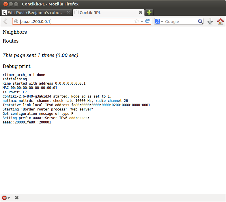
- Open a web browser and see if the webserver works by opening http://[aaaa::200:0:0:1]/. You should see something like this:
- In another terminal, go to examples/stm32-bv/test and run the following with the programmer connected to another mote:
make TARGET=stm32-bv clean
make TARGET=stm32-bv NODEID=6 PRINTF_VCP=0 upload
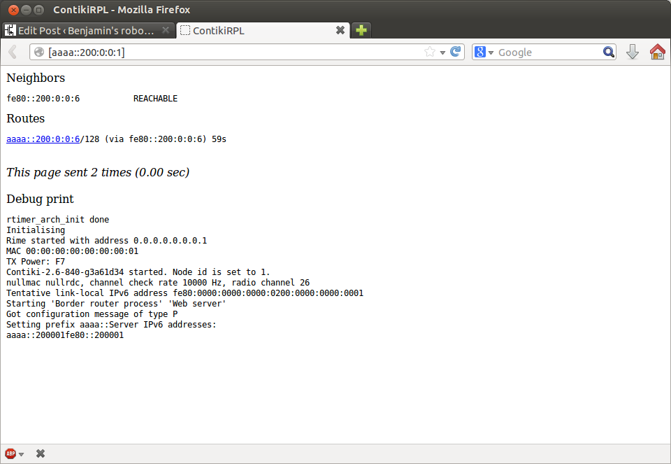
- After giving a few seconds for the routes to be built, try to ping the other mote:
ping6 aaaa::200:0:0:6
- Open the web page again http://[aaaa::200:0:0:1]/. You should see something like this:
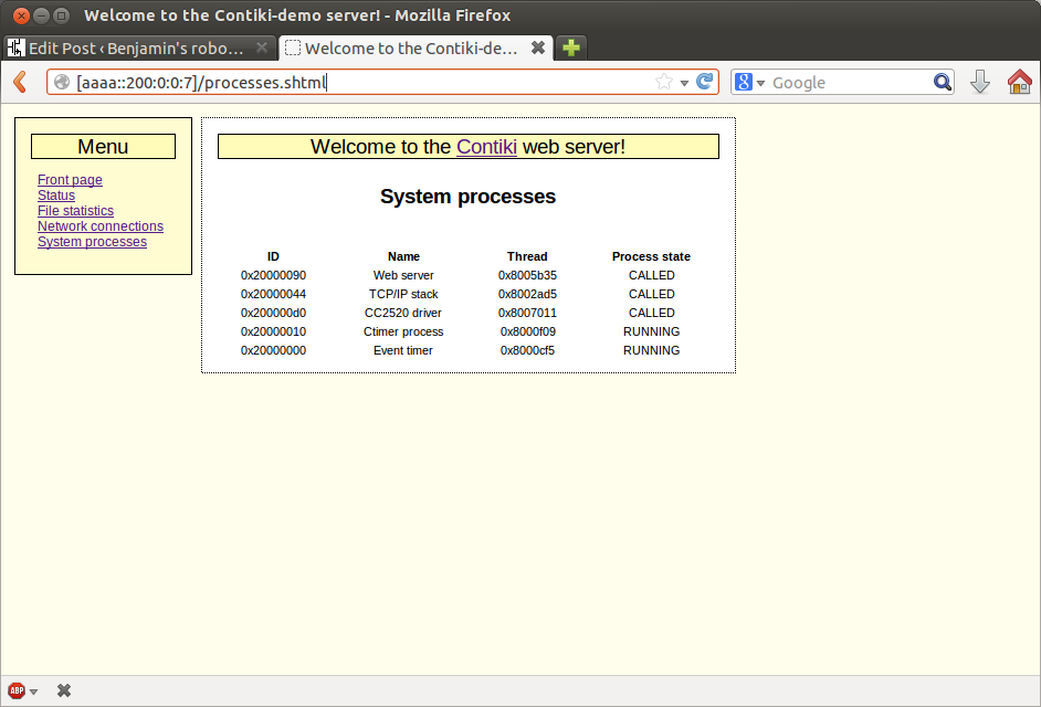
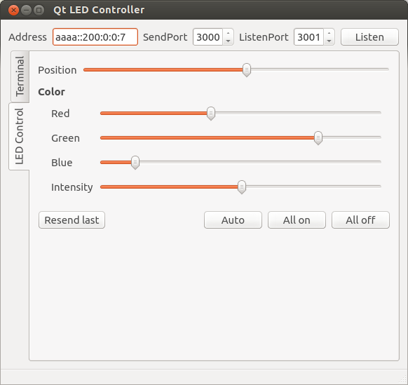
You can also try examples/stm32-bv/webserver-ipv6 on another mote. Then, if, for example, NODEID=7, you can open http://[aaaa::200:0:0:7]/processes.shtml in a browser and access a web page on that mote. That page should look like this:
Some notes about this usage example:
- In order to apply the passed arguments (e.g. NODEID=x), clean has to be run on the project first.
- The PRINTF_VCP-flag specifies that debug output should be redirected to the USB virtual serial port by default. When it is enabled, the program can freeze until the output is read, so if you don’t plan to use it, switch it off.
- The NODEID=x-flag will make x the last part of the IP address for that mote.
Another example
I have also made a simple driver for ws2811 addressable RGB LEDs. This driver uses DMA and a timer, so the CPU does not have to do anything. You can read more about ws2811 here. This example can be built and uploaded in the way described above. There is also a simple control client written in Qt that can be used to control the LEDs over UDP. This client looks like the following:
It can be build from the contiki/examples/stm32-bv/ws2811/QtClient directory by running:
qmake make ./QtLEDClient |
The data pin of the LEDs can now be connected to PB8 (pin9 on the header). Note a pullup-resistor (about 330 ohms) has to be connected to 5V from that pin since it runs in open-drain mode. This is because the ws2811 don’t work too well with a 3.3v signal.
This example shows all the parts that are required to implement a simple UDP server and a client that can be used from a desktop computer.
As the border router shows up as a network adapter, the application on the computer can use common network techniques to communicate with the devices in a seamless way. And this also works with multihop routing. Isn’t that cool?
Debugging
It is possible to start a GDB server with a simple command from this Contiki port. From the directory with the application you want to debug, run:
make TARGET=stm32-bv clean make TARGET=stm32-bv NODEID=7 DEBUG_BUILD=1 upload make TARGET=stm32-bv debug-start |
you should see something like this after the last command:
$ make TARGET=stm32-bv debug-start openocd -f ../../..//platform/stm32-bv/stm32-bv_openocd.cfg Open On-Chip Debugger 0.7.0-dev-snapshot (2013-08-05-13:24) Licensed under GNU GPL v2 For bug reports, read http://openocd.sourceforge.net/doc/doxygen/bugs.html adapter speed: 1000 kHz srst_only separate srst_nogate srst_open_drain Info : clock speed 1000 kHz Info : stm32f4x.cpu: hardware has 6 breakpoints, 0 watchpoints |
The DEBUG_BUILD=1 option will cause the project to compile without optimizations and the sleep mode of the stm32f4 disabled (if the core is sleeping, the debug interface does not work). Now you can connect to the GDB server in the usual way. Maybe I will write instructions about that later, but before that you might find some hints in this post.

nice work 🙂 any idea how to port stm32f105 ?? I have tried to change the memory config in linking script. doesnt work for me.
Thanks! Yes i have an idea about that, just follow the steps described above 🙂
well, seriously, I think you have to do a lot more than just changing the linker script. You have to adapt every driver to the peripheral library for the stm32f105; and many other things.
Hello! I’m trying to compile other examples like “sky-shell” and i got some errors about undefined references at linking :
sky-shell.co: In function `process_thread_sky_shell_process’:
sky-shell.c:(.text+0x1c): undefined reference to `shell_sky_init’
collect2: error: ld returned 1 exit status
make: *** [sky-shell-nosyms.stm32-bv.elf] Error 1
rm cc2520-arch.o interrupts-cpu.o syscalls.o sky-shell.co
did you modify other things in he code of the examples that you propose?
Thanks in advance!
Hi,
I just tried to build it, and the reason that it does not compile is that the function shell_sky_init is for Tmote Sky-specific Contiki shell commands (such as for reading the sensors on that mote, sensors which are not present on the stm32-bv mote). You can comment that line out and it will compile with the stm32-bv target. I also tried to build it with the sky target, and that works, so there is nothing else that is modified in my Contiki port.
Ok! thanks!
Otherwise I’ll use your schema for build another version of your board, with an SPI flash memory and other sensors, like in the stm32f4discovery board. Have you tested basic funcionality of the coffee file system? Anyway I think a driver must be written, based on some other board (maybe sky or z1) or maybe take the SD reader from the stm32f103…
I haven’t tested the coffee file system, but it should work with the flash memory and I don’t think it is too difficult to set up. I was also planning to run the board as an USB host and use an USB memory stick as storage. I have most of the code ready for that in other projects, but I haven’t done it yet.
Would you be interested in ordering a couple of similar boards ready assembled together? Many people have asked me about that, so I’m thinking about modifying the hardware a bit (adding a CAN transceiver and more IO ports) and making a group order of maybe 100 – 200 pieces. We can of course discuss what we would like to add to the hardware.
Yes! I’m very interested. I’m adding the SPI flash M25P16 (2Mbyte) a microSD connector and an SHT15. I would like to add some ports for other kind of sensors (like the zolertia z1 3-pin). We can discuss by email if you want: francisco.acosta(at)inria.fr
Sure!
I will send an email as soon as I have time. Anyway, I don’t want to add too much hardware at the moment to keep the size minimal. The SPI flash seems a bit redundant since the STM32F4 already has 1MB built-in flash, but we can discuss that.
Great! Yes, I agree that 1MB seems to be a lot of memory, but for my application it could be filled only with program code. I’m thinking about change that memory for another one of 32Mbyte size, since I don’t want to use an SDcard (and deal with FAT in contiki) mandatory… well, we’ll discuss all this. Thanks in advance!
Hello again!
Just to finish my example board, do you have the libs and mods that you used? I’m trying to find them in the web but some are a bit difficult to obtain… Thanks!
Sure! You can download them here:
http://home.vedder.se/public/kicad/
I’m not sure if you need all of them though.
Hi again, I’m sorry to bother you again, but what version of contiki have you ported to the boards?
Thank You
Hi,
You are not bothering me at all. It is nice to see that you are interested in my work 🙂
I forked the master branch of contiki. Just now I made a merge with the latest upstream version, so it would be 3.x. I also made sure that everything compiles after the merge and tested the webserver and border router.
Pingback: CC2520 and STM32 RF boards | Benjamin's robotics
hey can you give me some instructions on how to port contiki to an arduino? i just need to know what sort of file i should change and how to change them. also is there a way to program contiki so that we can run stuff like a PWM program on the microcontroller? thanks in advance
Hey, just wanted to say thanks for all the information you’ve posted on your stm32/cc2520 boards and software for them. I just finished making my first revision of a board based on a STM32F103 and CC2520 combo – and your software was a great help in getting that to work. Still have to do more testing on mine; haven’t had a chance to measure outdoors range yet and don’t have access to equipment to do a proper power measurement; but it is at least basically functional and can cover my house (although it isn’t a particularly big house).
Nice work! Regarding the power performance, if you copied the TI layout with 0402 components and use similar trace shapes on a 0.5mm PCB with 35µm copper, it should work quite well. If you have a PCB antenna, then you probably have to tune it before you get full performance. There are some guide on how to do that, but you also need some expensive equipment. The simplest and best way is to use a SMA connector and a separate antenna – if you have the space available.
The layout isn’t based upon TI’s reference design; I decided to use a single piece balun/filter made for the CC2520 (http://www.johansontechnology.com/datasheets/balun-filter/2450BM15B0002.pdf) and is based on the documented design for that; their documentation isn’t as detailed/clear as the TI designs though. I was hoping to avoid the complexity of the TI design, both in terms of the layout as well as the requirement for getting thin PCBs made.
Where did you get your thinner PCBs made, just wondering in case I decide to redesign based upon the TI reference design. How is the quality? I typically use OSHPark, but they only do 1.6mm boards. Would also have to get new SMA connectors as my current ones are edge mount ones for 1.6mm boards.
I haven’t seen that solution, but it might work (I’m not an expert on high-frequency RF). I used the TI layout and noticed that it didn’t work well with 1.6mm PCBs; and that changing to 0.5mm as in the TI design helped a lot.
This is where I have ordered most PCBs recently:
http://www.hackvana.com/store/
The prices are good and Mitch is really friendly. Definitely recommended!
Yeah, I’m not an expert in RF circuit design (or circuit design in general even; my training is in computer science on the software side); but I know enough that I knew the TI reference design wouldn’t work on 1.6mm boards – would throw off the characteristic impedance of the 50ohm trace too much (and probably mess with the other characteristics as well).
Once I get a chance I’ll measure my outdoors range on the two that I have built and working; that should at least give me some idea how well my attempt at using the integrated balun/filter worked. If the results are too poor then I can consider reworking based upon the TI reference design. I can at least work on the software in the meantime.
Again, thanks for the feedback and all the great information you post about your stuff. At some point I’m going to get my own site setup to post my own things (at least I keep telling myself that).
Dear
Thanks for sharing.
Is it possible to buy a compete tool for teaching.
Best regards
Hi,
Unfortunately I don’t have any assembled kits that I can sell. The circuit board and all the components for my rf boards are about 20€ in total, but they still need to be assembled (soldered). For my test boards I did this by hand, but in order to buy assembled boards I have to order quite large quantities to get a low price. If there is enough interest I will try to create a complete kit some time.
Ordering a small batch (about 5 to 20) of ready assembled would cost about 100€ for each board, but if you are interested I could try to arrange that.
/Benjamin
Hi Benjamin
Thank for your reply.
I will keep you inform for the quantity.
This board (A custom BLDC motor controller ) is also very insteresting Can you give some estimation cost?
Thanks in advance.
The BLDC-controller is probably the project I have spent the most work on (especially the code), so I hope that I will get the chance to make it available for everyone at some point 🙂
A very rough estimate for 5 to 20 assembles BLDC-controllers is 100€ to 200€ for every peice. The components and the PCB are about 30€, but here again the dominant part of the price is for the assembly with such small quantities. What I did was to order bare PCBs and all the components and assemble it myself, which isn’t too difficult, but most people are not comfortable with soldering small SMD parts by hand.
If you feel like giving the hand assembly a try, here is a good tutorial:
http://www.youtube.com/watch?v=3NN7UGWYmBY
In addition to the equipment in the video, you also need a hot air soldering station to solder the chips with a pad below.
/Benjamin
Benjamin
Thank you very much!
I have got useful information!
For buying, i think, public funding generally need a quote and many others information. Did you have some structure for business?
For RF board, I think it will be very interesting to have cc2520 only board which can be connected to stm32F4discovery board or others. For my labs I have already 30 stm32F4discovery and it will be difficult to get funding for another stm32F4 board.
So my question is : It is possible to have your board without the MCU parts?
Best regards
Hi again,
I am working with the stmf105 port based on your post.I managed to port everything. I am using arm dbg-io for slip and printf. I want to remove syscalls.c from my source. But my compiler gives errors
undefined reference to `_sbrk’
undefined reference to `_write’
How can I remove syscalls.c ??
Another problem I have is with stm interrupt. seems like my contiki processes are hanging for some reason. can we talk over email. I shall be happy to support you work 🙂
Hi,
printf uses the _write system call to output data and _sbrk is used when printf uses malloc internally. There has to be a connection between your linker script, the startup code and _sbrk because _sbrk needs to know the size and locations of the stack and the heap when malloc allocates memory. Why would you like to get rid of the syscalls file? You can simply keep the _write function in syscalls.c and route it to dbg-io, like the way I routed it somewhere else.
Regarding the interrupts, the system usually hangs when the default interrupt handler is called because it is an infinite loop. I had a problem with overriding the default weak interrupt handlers in the contiki build system because everything is linked together in a static library. The weak interrupt handlers won’t be overridden by this library properly. Therefore, I had to compile all code with interrupt handlers in a special way. Have a look at INTERRUPT_SOURCEFILES and INTERRUPT_OBJECTFILES in this file:
https://github.com/vedderb/contiki/blob/master/cpu/arm/stm32f4/Makefile.stm32f4
Sure, we can talk over email as well.
/Benjamin
Hi Benjamin !!!
Good work 🙂
I f I am not mistaken. there should not be any problemin using this port of Contiki to cc2520+stm32f4 board for stm32f4 discovery board??
Hi,
Thanks!
That is correct, it should work right away with the discovery board.
Hi!!
I am trying to use this Contiki port for stm32f4 discovery board. hello-world application compiles but after programming it on the board and connecting USB OTG cable, I am not able to see anything on gtkterm. Moreover, I have changed platform/stm32-bv/leds-arch.c file so that port D (where leds are connected on discovery board) may be initiated. After doing the change, I tried to program board with examples/stm32-bv/test/hello-world application(comented cc2520 related lines), but led does not toggle on board.. Can you help me in identifying the problem that I am facing right now. Thanking in anticipation.
Hi,
I don’t have a discovery board here at the moment, but I will give it a try next week. I think that what you did should work, but maybe you have to disable the cc2520 initialization in contiki_main.
Yup, things work after disbaling cc2520 initialization 🙂
I want to use wifi discover module with stm32f4 discovery board … What should be starting point of adding such support in Contiki ?
Thanks
Hi AZ,
May I know your contact mail i.d please. Even I’m working on the same platform having few doubts and required to get it clarify.
Hi!!!
I’ve seen two posts:
+A Contiki port for my custom cc2520+stm32f4-boards
+Play MP3 on the STM32F4 Discovery
it was great!!!
And now,I am trying to use this Contiki port for stm32f4 to play MP3,you can give me some guidance?
Hi Benjamin, I stumbled upon your post while googling. Thanks for doing a great job with all the information.
Do you have any ready-made boards with you, like 2-5 of them that I can buy? Please let me know. I hope my email address is visible to you, please feel free to reply there.
Again, thanks for all the great work.
Benjamin,
Thanks so much for your post. It is VERY VERY helpful. -Val
Hi Benjamin,
I am trying to create a port for Contiki to lpc1347, it would be great if you could help me. Lpc1347 has the Cortex-M3 architecture, contiki does not have device driver API. Also, when you were developing microcontroller specific codes, how were you debugging them, what linker script were you using? i am using the script on (https://github.com/microbuilder/LPC11U_LPC13U_CodeBase) and it is giving me an error.
I am new to this and you post is helping me out a lot.
Never mind, i rectified the error, the problem now i am having is a hard fault, the address of hello_world thread is not recognized by the mcu. The other processes were running fine though. Whomever i ask say it is some initialization error, but the initialization part (creating thread and running it when it is added to autostart) is done by contiki libraries. Could it be because of an error in makefile or linker script (i do not have an sd card or any memory storage in my board). It would be great if you could share your insights on this problem.
In rtimer_arch.c , you have used TIM7 and it doesn’t have CCR, i.e u can’t use TIM_SetComapare() , i am curious how does this work??
Pingback: Links Related to Contiki OS | haripds
Hi,
Your work is very interesting. Congratulations.
I have a question for you:
Did you have any troubles with the cc2520 driver? I have notived that your driver is a little bit changed, and I am not talking about the architectural changes.
I am trying t do something as you did, but my problem now is the CC2520.
All the responses I have from the chip are 0x80, 0x81, sometimes 0xC1, others 0x00 but I never get the transceiver to send any packet.
i tried to compile and run your radio-test example, but it didnt send any packet either. Trying to “sniffing” with an logical analyzer the SPI lines, I can only see 0x00 going on.
It would be good to share some ideas with you.
Write me if you can.
Regards,
Hi Benjamin,
I have gone through your post. It is very informative and thank you for all members who participated in this communication. I am very new to this field and I am planning to port contiki for TelosB. I have uploaded the hello-world and broadcast example in TelosB. It works perfectly but now I am thinking for multihop communication. I need your guidance for porting contiki. I would be grateful for any kind of suggestion.
Thank you
Best Regards