Post updated 2016-01-22
About this project
I have made many updates to my custom motor controller recently and the old post is getting confusing with notes and updates, I decided to write a new post about it that hopefully is more clear, more complete and easier to follow. This might sound a bit ambitions, but my goal is to make the best ESC available. I really enjoy sharing knowledge, so I want to keep all the hardware and software open.
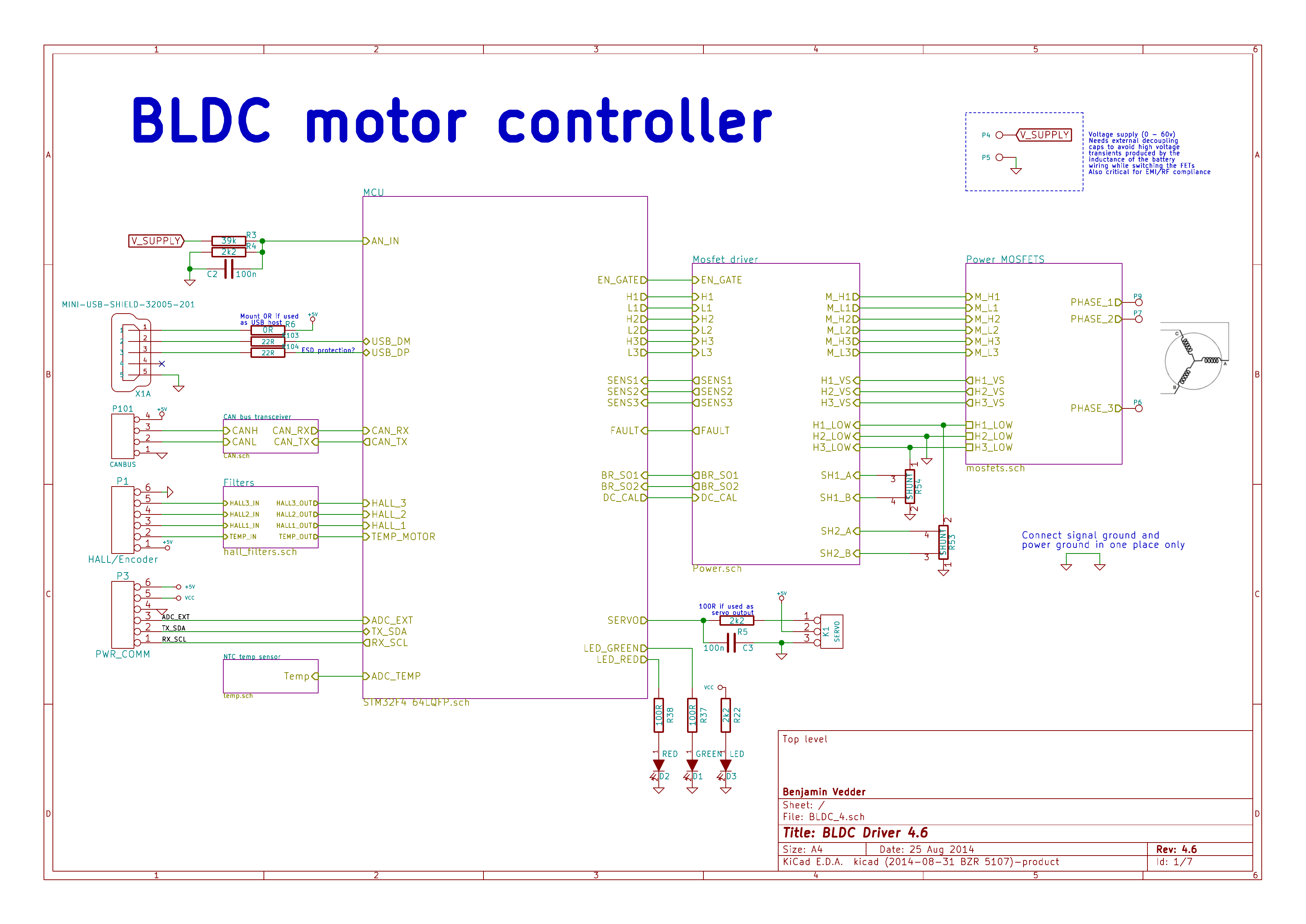
This is an overview of the schematic (download a complete PDF here):
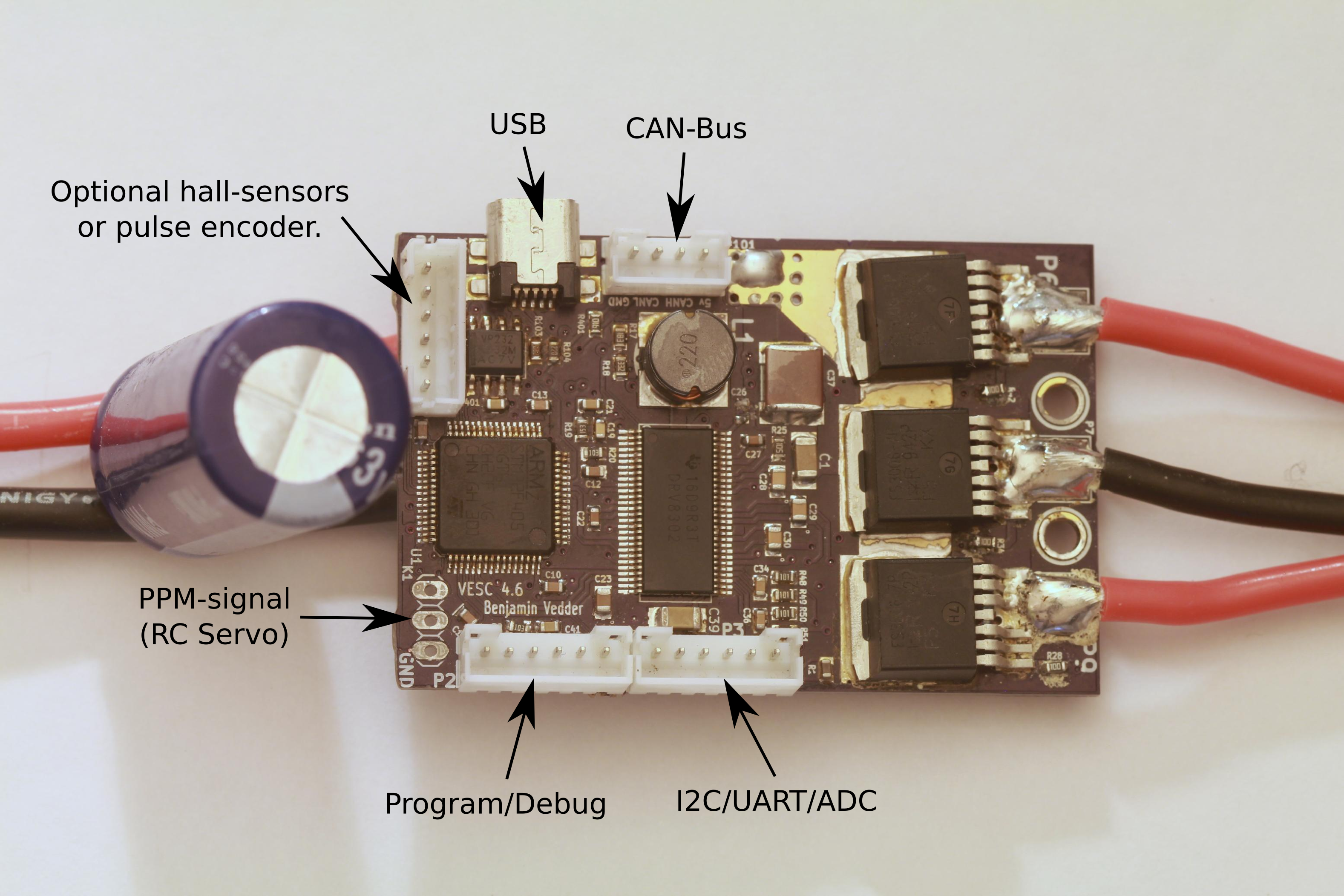
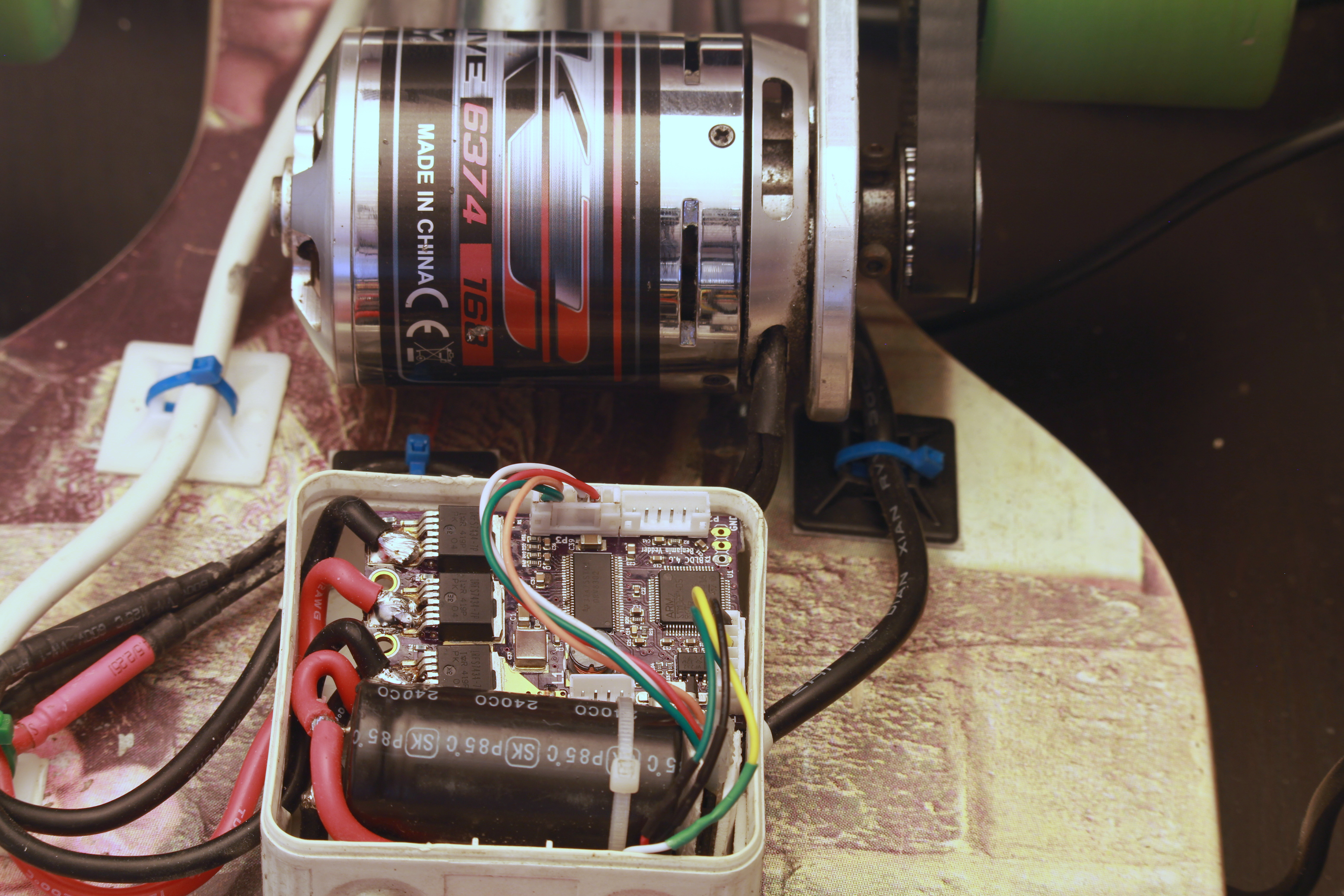
This is the front of the PCB:
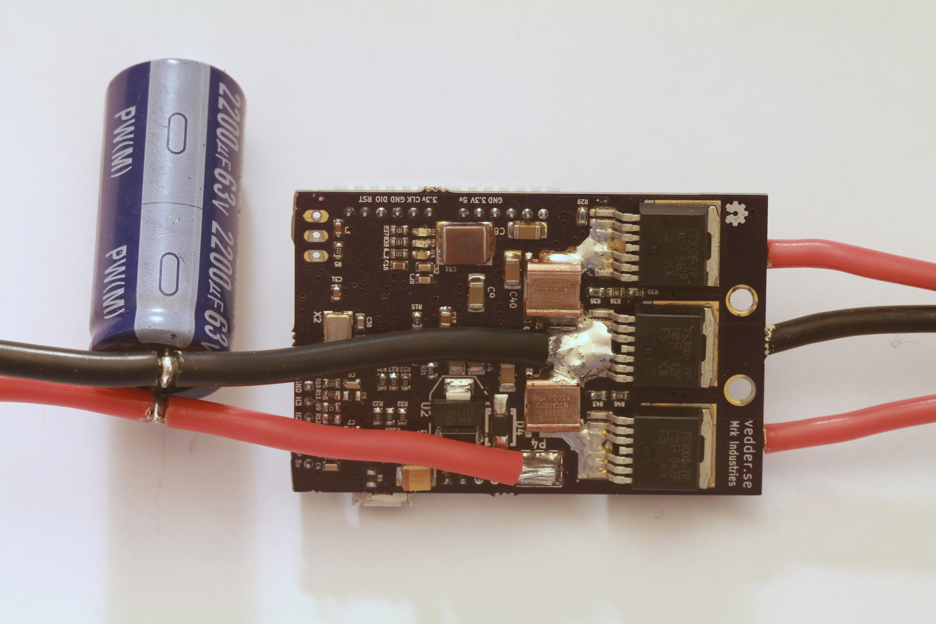
The back:
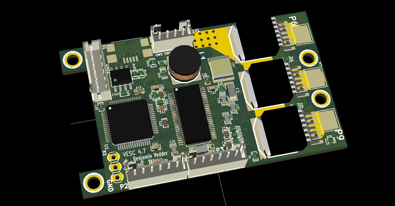
3D render from KiCad:
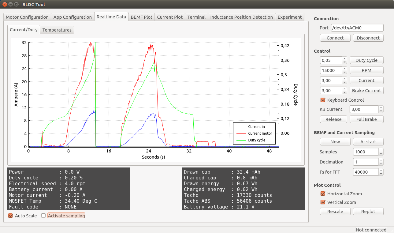
Some screenshots of the configuration GUI (BLDC Tool):
Resources
All files are on github to keep them up to date, so check these links on a regular basis:
- Hardware design
- Bill of materials
- Firmware
- Configuration GUI
- Video logger
- osx and windows builds of BLDC Tool, Video logger etc. by Jacob Bloy
Related posts
- Old post motor controller (just for reference)
- Video overlay logging
- Electric skateboard motor tutorial (KV, cells, etc.)
- Startup torque
- Hardware debugging
- Making a programmer
- Writing custom applications
- UART Communication
Forums
Because information about the VESC is scattered all over the internet and a lot of information is in email conversations with me, I have created a forum dedicated to the VESC here.
Live Chat
I have created an IRC channel on freenode where you can live chat with me and other users about VESC and my other projects. Feel free to join: http://webchat.freenode.net/?channels=vedder
Features
- The hardware and software is open source. Since there are plenty of CPU-resources left, the customization possibilities are almost endless.
- STM32F4 microcontroller.
- DRV8302 MOSFET driver / buck converter / current shunt amplifier.
- IRFS7530 MOEFETs (other FETs in the same package also fit).
- 5V 1A output for external electronics from the buck converter integrated on the DRV8302.
- Voltage: 8V – 60V (Safe for 3S to 12S LiPo).
- Current: Up to 240A for a couple of seconds or about 50A continuous depending on the temperature and air circulation around the PCB.
- Sensored and sensorless FOC wich auto-detection of all motor parameters is implemented since FW 2.3.
- Firmware based on ChibiOS/RT.
- PCB size: slightly less than 40mm x 60mm.
- Current and voltage measurement on all phases.
- Regenerative braking.
- DC motors are also supported.
- Sensored or sensorless operation.
- A GUI with lots of configuration parameters
- Adaptive PWM frequency to get as good ADC measurements as possible.
- RPM-based phase advance (or timing/field weakening).
- Good start-up torque in the sensorless mode (and obviously in the sensored mode as well).
- The motor is used as a tachometer, which is good for odometry on modified RC cars.
- Duty-cycle control, speed control or current control.
- Seamless 4-quadrant operation.
- Interface to control the motor: PPM signal (RC servo), analog, UART, I2C, USB or CAN-bus.
- Wireless wii nunchuk (Nyko Kama) control through the I2C port. This is convenient for electric skateboards.
- Consumed and regenerated amp-hour and watt-hour counting.
- Optional PPM signal output. Useful when e.g. controlling an RC car from a raspberry pi or an android device.
- The USB port uses the modem profile, so an Android device can be connected to the motor controller without rooting. Because of the servo output, the odometry and the extra ADC inputs (that can be used for sensors), this is perfect for modifying an RC car to be controlled from Android (or raspberry pi).
- Adjustable protection against
- Low input voltage
- High input voltage
- High motor current
- High input current
- High regenerative braking current (separate limits for the motor and the input)
- Rapid duty cycle changes (ramping)
- High RPM (separate limits for each direction).
- When the current limits are hit, a soft back-off strategy is used while the motor keeps running. If the current becomes way too high, the motor is switched off completely.
- The RPM limit also has a soft back-off strategy.
- Commutation works perfectly even when the speed of the motor changes rapidly. This is due to the fact that the magnetic flux is integrated after the zero crossing instead of adding a delay based on the previous speed.
- When the motor is rotating while the controller is off, the commutations and the direction are tracked. The duty-cycle to get the same speed is also calculated. This is to get a smooth start when the motor is already spinning.
- All of the hardware is ready for sensorless field-oriented control (FOC).
Writing the software is the remaining part. However, I’m not sure if FOC will have many benefits for low inductance high-speed motors besides running a bit quieter.Sensored and sensorless FOC is fully implemented since FW 2.3.
The is the ESC mounted on my electric longboard:
Sensorless startup and low-speed performance:
A short tutorial/demonstration on how to upload the firmware and get your motor running:
My electric longboard:
Video overlay logging (see a post about that here):
Hardware
The PCB is designed using KiCad. Have a look at the links under the Resources heading at the top of this page to find all files. Currently I have no assembled PCBs or kits to sell, but you can order bare PCBs from hackvana with these gerber files. Since hackvana got so many orders for my ESC, Mitch wrote a wiki page about how to order VESC boards from him. That makes it super easy to order the PCBs from him.
The components in the BOM can be ordered from mouser.com. Mouser numbers are included in the BOM as well. Make sure to order a bit extra of small capacitors and resistors in case you drop some of them and since the price doesn’t change much at all. Last I ordered, ordering 10 MOSFETs was cheaper than ordering 6 because there is a price break at 10, so have a look at the price breaks as well.
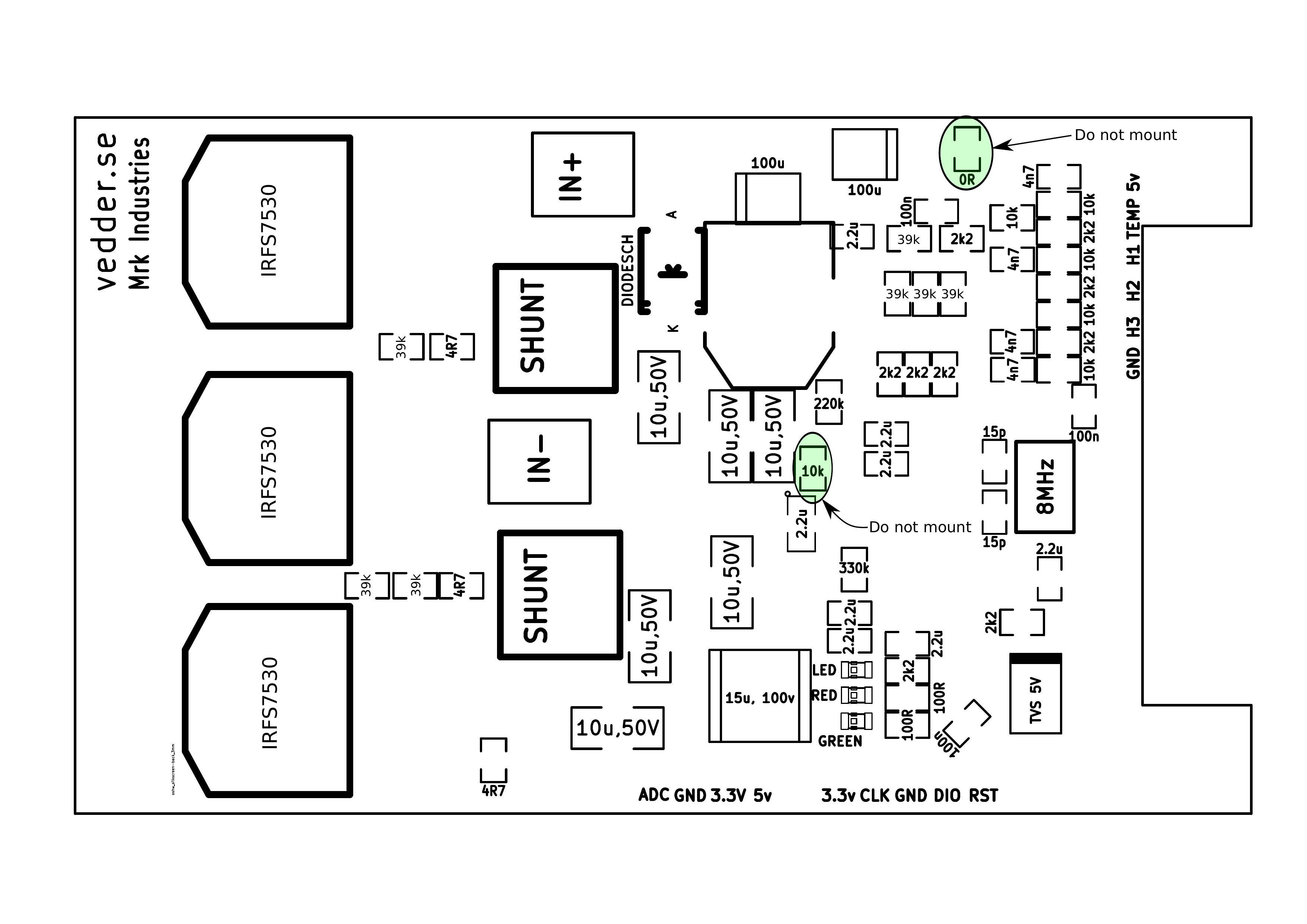
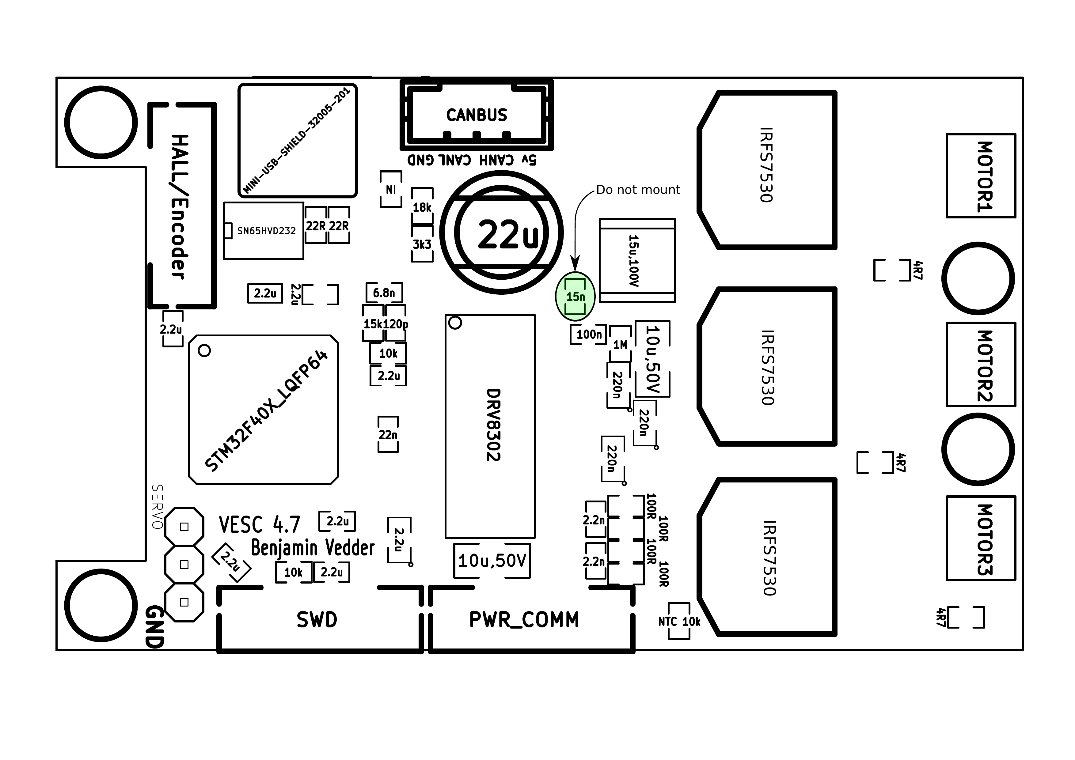
For assembling the PCBs, the following pictures are useful (the latest versions can be found on github):
Remember to put an electrolytic capacitor close to the ESC on the supply cable. How large it has to be depends on the length and inductance of the battery cables, but I usually use a 2200uF 63V capacitor.
Soldering Tips
This is the best tutorial I have seen so far. It really is as easy as it looks when done right.
- Flux is essential. Without flux, it won’t work. I use a flux pen.
- Lead-free solder is no good. It has more poisonous flux, requires more heat, gives lower quality and is difficult to handle. Don’t use lead-free solder.
- Use a flat, screwdriver-shaped tip. Don’t use a cone tip, because putting solder on the top of it is almost impossible.
- If you get bridges between smd pins, removing them is easy with a soldering wick.
- Make sure to get the alignment right for the microcontroller when soldering the first corner. If you solder multiple corners and the chip is misaligned, you have to use hot air and remove it, then clean the pads and start over.
Here is a video on the technique I use to solder the pad under the DRV8302:
I just put solder on the pad and use a hot air soldering station. Again, using leaded solder makes it easier. When soldering the DRV8302, I first solder the pad using hot air and then I solder the pins with a soldering iron. Notice that the pad under the DRV8302 must be connected for it to work, since it is the ground connection.

VESC Hardware by Benjamin Vedder is licensed under a Creative Commons Attribution-ShareAlike 4.0 International License.
Software Installation and Configuration Tutorial
This a brief tutorial on how to get everything running using a fresh install of Ubuntu 14.04. Here is a video where I do everything live to demonstrate that it isn’t that difficult. Please read all the instructions carefully to avoid most problems.
So let’s open up a terminal and get started…
Preparations
Install a toolchain to compile the firmware (for more details, have a look at this page):
sudo apt-get remove binutils-arm-none- eabi gcc-arm-none-eabi sudo add-apt-repository ppa:terry. guo/gcc- arm-embedded sudo apt-get update sudo apt-get install gcc-arm- none-eabi= 4.9.3.2015q3- 1trusty1
Install other dependencies
sudo apt-get install build-essential qt-sdk openocd git libudev-dev libqt5serialport5-dev
Add yourself to the dialout group to access the USB port of the ESC without being root:
sudo adduser $USER dialout
Uninstall modemmanager (unless you use it) to avoid a delay every time the ESC is plugged in to the USB port:
sudo apt-get remove modemmanager
Add udev rules to access the programmer without being root:
wget vedder.se/Temp/49-stlinkv2.rules
sudo mv 49-stlinkv2.rules /etc/udev/rules.d/
sudo reload udev
Log out and log back in. You should now be ready to compile the firmware, upload the firmware, compile BLDC Tool and run BLDC tool.
Download, Compile and Upload the Firmware
First, connect a programmer as described in this post. Then, download the latest firmware from github, compile and upload it:
mkdir BLDC
cd BLDC
git clone https://github.com/vedderb/bldc.git bldc-firmware
cd bldc-firmware
make upload
cd ..
Note: before running the make upload command, you should open conf_general.h and select which hardware version you are using. It is printed on the PCB. Also, 2015-01-22 I changed the voltage divider resistors to allow up to 60V to be measured by the ADC, so in that case you also have to override VIN_R1 to 39000.0 in conf_general.h.
Download, Compile and Upload the Bootloader
Again, connect a programmer as described in this post. Then, download the latest bootloader from github, compile and upload it:
mkdir BLDC
cd BLDC
git clone https://github.com/vedderb/bldc-bootloader.git bldc-bootloader
cd bldc-bootloader
make upload
cd ..
With the bootloader, BLDC Tool can be used to upgrade the firmware later.
Download, Compile and Start BLDC Tool
From the BLDC directory that you created in the previous step, type:
git clone https://github.com/vedderb/bldc-tool.git bldc-tool
cd bldc-tool
qmake -qt=qt5
make
./BLDC_Tool
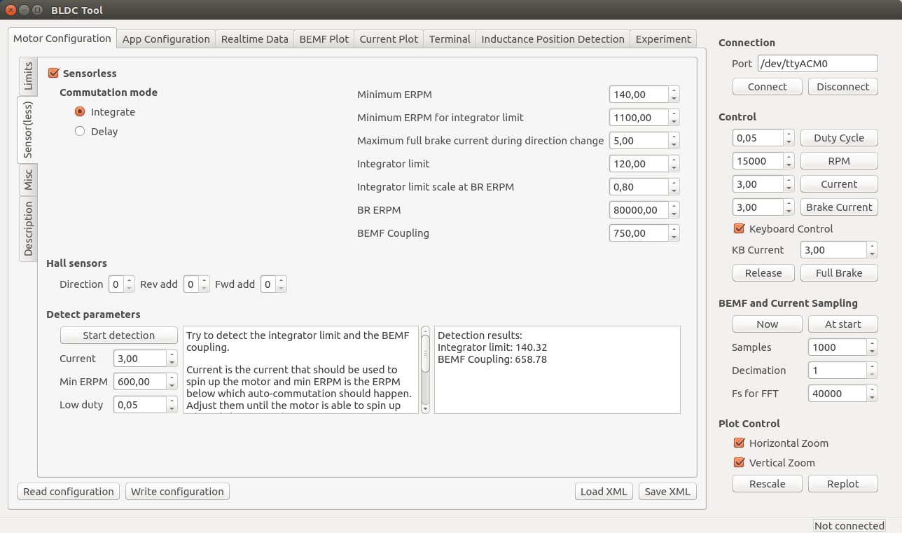
You should see the following screen:
Connect the ESC to the USB port of your computer and click “Connect” in BLDC Tool. The lower right corner should now say “Connected”. If you have gotten this far, you should be ready to connect a motor and configure the ESC from BLDC Tool.
Note: If you have more than one usb-modem device in your computer (laptops often have built-in 3g modems), then you have to change ttyACM0 to the port of the ESC. To figure out which ttyACMx port the ESC got, open a terminal and type the following command right after plugging the USB cable in:
dmesg | tail
BLDC Tool can also be started by going to the bldc-tool directory with a file browser and double-clicking on “BLDC_Tool”.
Updating to the Latest Firmware
Updating to the latest firmware and the latest version of BLDC Tool is rather simple. From the bldc-firmware directory, type the following commands while the programming cable is connected to the ESC:
git pull
make upload
Note: Updating the firmware will delete the configuration of the ESC. To save it from BLDC Tool, use the “Read configuration” button and then “Save XML”. After updating the firmware, you can restore it with “Load XML” and “Write configuration”.
Also updating BLDC Tool is important and recommended at the same time as updating the firmware. In order to do that, go to the bldc-tool directory and type:
git pull
qmake
make
Now you have the latest version of the firmware and BLDC Tool. Remember to reconfigure the ESC after these changes.
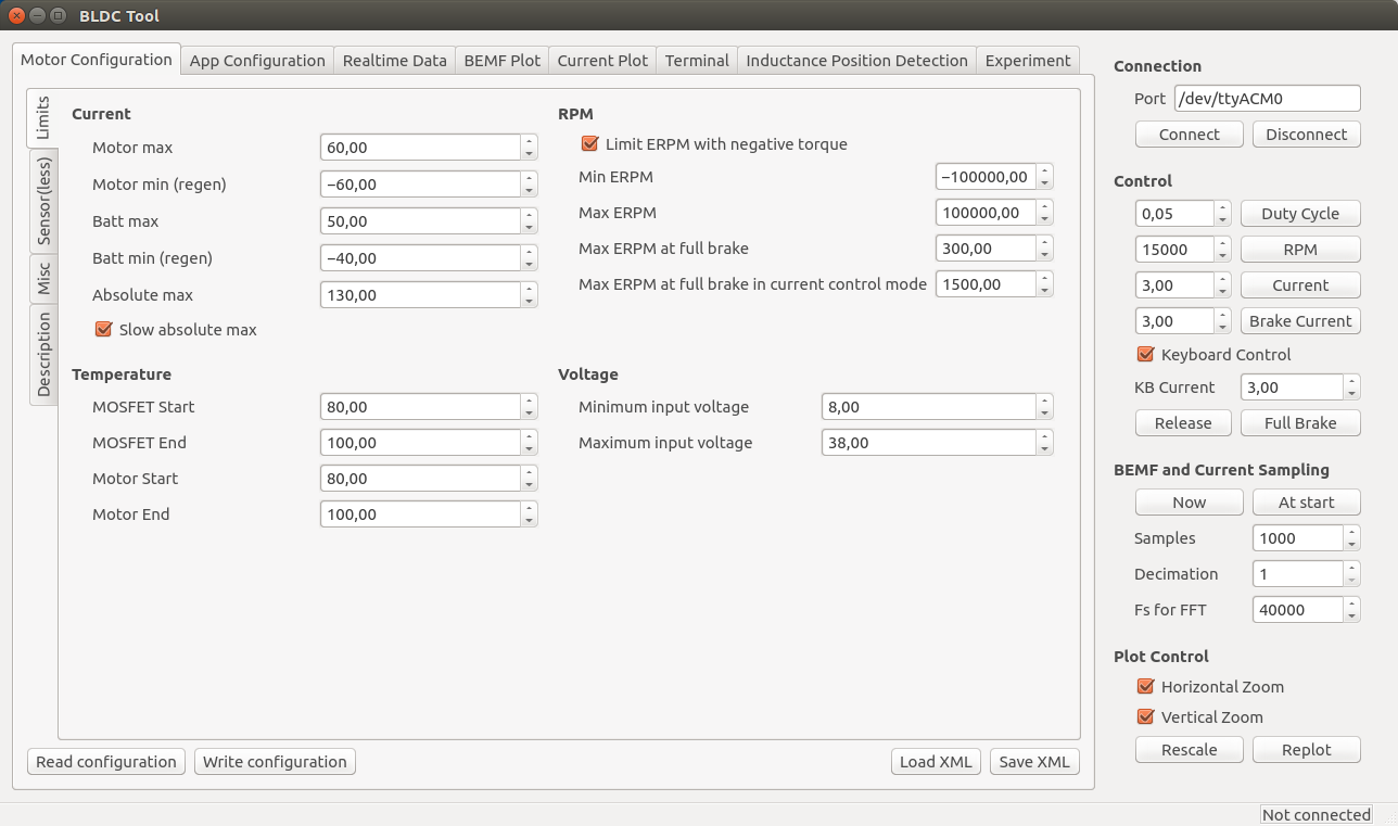
Motor Configuration
Note: During the configuration, it is assumed that the USB cable is connected to the ESC and that the lower right corner of BLDC Tool says “Connected”.
The first thing to do in the “Motor Configuration” tab is to click “Read configuration” while the ESC is connected to get the current configuration. After that, click “Load XML” and look for a configuration that is the same as or similar to your motor in the “mc_configurations” folder included with BLDC Tool. If you find exactly your motor, you don’t have to change anything unless you want to tweak some parameters for your application.
Note: Even if you load an XML configuration file, use “Read configuration” first anyway because the XML might not contain all parameters. The missing parameters will become blank and can mess with things. Soon I will make sure that sane default parameters are loaded, but I haven’t done that yet.
Sensorless Motor Parameters
Since this ESC uses uncommon techniques to commutate the motor in order to get good low-speed performance without sensors, it is important to set correct motor-dependent parameters in the sensor(less) tab. Otherwise, the motor will run poorly or not at all.
This is what the Sensor(less) configuration page currently looks like (I will probably add more auto-detect options soon):
The important motor-dependent parameters are “Integrator limit” and “BEMF Coupling”, and they can be measured with the detection part. I will make a video showing this for several different motors soon, but until then you can try to follow these instructions:
- Connect the motor without any load and make sure that it can spin up freely.
- Make sure that no other input such as PPM is used. If it is, it will stop the motor immediately when the detection tries to start it and the detection will fail.
- Click the “Start detection” button. The motor should spin up, release throttle and then run slowly for a moment.
- If the motor doesn’t spin up properly, Adjust “Current” and “Min ERPM” until it does. In general, small motors should have lower current and higher ERPM and larger motors the other way around. Current usually is in the range 1A to 6A and min ERPM usually is in the range 300 to 1200.
- If spinning up works but running slowly afterwards doesn’t (the motor just stutters), try increasing “Low duty” to 0.1 or so. Increasing low duty will make it easier for the motor to run slowly during the test, but the result will become less accurate.
- Manually put the obtained values into the boxes. I usually round “integrator limit” down to the closest multiple of 5 and “BEMF Coupling” down to the closest multiple of 50. Having them slightly lower than the detection result is good in most cases, so that’s why I round them downwards like that. Getting these parameters perfectly right is not too critical though.
- The next parameters to adjust are “Min ERPM” and “Min ERPM for integrator limit”.
- What they should be depends on the application and is in most cases not too important, but in general lowering them will work better if the load has much inertia. I have Min ERPM around 200 and Min ERPM for integrator limit around 1000 for all my applications.
- You can probably keep the same parameters I have, but if you want to tweak your startup you can experiment with them.
- It is important that “Min ERPM” always is lower than “Max ERPM at full brake” and “Max ERPM at full brake in current control mode” on the “Limits” page.
- Commutation mode should always be “Integrate”.
- The other parameters are for RPM-based timing advance and some other things that aren’t necessary to adjust in the normal case, so I won’t explain them here yet.
For small low-inductance high-speed motors, the delay commutation mode can be used in case the integrate mode does not work. It does not require many parameters, just the minimum RPM which usually can be around 1500. I haven’t tested this mode much, but it is more or less how most hobby ESCs work (which is why it doesn’t require so many motor-specific parameters). Currently it does not support adjustable timing, but I will implement that in a few days since it is quite easy.
Phase advance (other terms: timing adjustment, field weakening)
To compensate for the current lagging behind the voltage at high speeds because of inductance or to get a bit higher top speed at the expense of some efficiency and torque, phase advance can be used. It is implemented in a speed-dependent way so that the motor gets more phase advance the faster it spins. It is implemented this way because having phase advance at low speeds does not give any improvements at all as far as I know, so the best way is to increase the effect as the motor increases its speed. BR ERPM is the electrical RPM of the motor at which the set phase advance is used, and Integrator limit scale at BR ERPM (will rename this option soon…) is the amount of phase advance to use. Setting it to 1.0 gives no phase advance and setting it to 0.0 gives 30 degrees (maximum) phase advance. The set phase advance will be mapped linearly between 0 ERPM and BR ERPM. If you don’t know what this is, you can leave the default options since it is not that important.
Motor
Current, temperature, RPM and voltage-limits can be configured depending on your application.
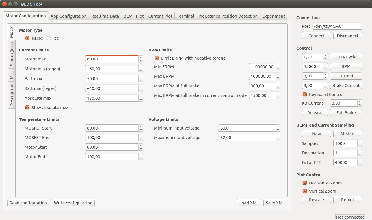
Note: These limits are not foolproof. If you set them too high, you can damage the ESC and/or the motor.
- Current
- Separate limits for acceleration and braking current.
- Separate limits for motor and battery currents.
- “Absolute max” is checked in every PWM switching cycle and used in case the soft back-off strategy for the other limits doesn’t work. I usually set it way higher than the other limits because soft back-off is preferred rather than switching off the motor with a fault code, but it should never be higher than 150A.
- The “Slow absolute max” box will make sure that a filtered version of the maximum current limit is used. This is useful if there is much noise and that fault code kicks in all the time. I usually have it ticked.
- Temperature
- At the “Start” temperature, the current will become more and more limited linearly until the “End” temperature, where the output is switched off completely. Setting them about 20 degrees apart will make the ESC slowly decrease the maximum output current as it gets too warm instead of abruptly switching everything off.
- MOSFET temps (on the ESC) are implemented and working, but motor temps are not implemented yet. They will require an external temperature sensor in the motor. The software implementation is rather simple since I can just copy most of the MOSFET temperature limit code.
- RPM
- Max and Min ERPM are hard RPM limits. It is preferable to use the soft application RPM limits instead if possible.
- “Max ERPM at full brake” (should change the name…) is the highest opposing RPM at which a direction change is allowed. Setting this too high will cause cogging when moving in one direction and giving high throttle in the other direction. On my longboard I have it at 300 and my RC car has it a bit higher.
- “Max ERPM at full brake in CC mode” is the highest RPM at which applying full brake by shorting all the motor windings is allowed. Setting this value too high can cause much mechanical stress in some circumstances. I have it at 1500 for all my applications.
- Voltage
- The minimum and maximum input voltage.
- NOTE: I changed the voltage dividers in hardware 2015-01-22. If you have built the PCB before that, the maximum voltage can’t be more than 52V. The difference is whether the PCB has 33k or 39k resistors. 33k means that maximum 52V can be measured. The latest PCBs (with 39k resistors) can measure 60V, but you should have some margin on your supply voltage to be safe. You can of course replace all 33k resistors with 39k and measure up to 60V.
Once the ESC is configured for your motor, you can use the up and down arrow keys to run the motor forwards or reverse in current control mote, or the right and left arrow keys to run the motor forwards and reverse in duty cycle mode. The buttons in the right-hand side of the GUI can also be used.
Misc
Here are the rest of the motor configuration parameters. You probably want to experiment with Startup boost if you are using current control. The rest of the parameters can be left as their default values unless you have some specific reason to change them.
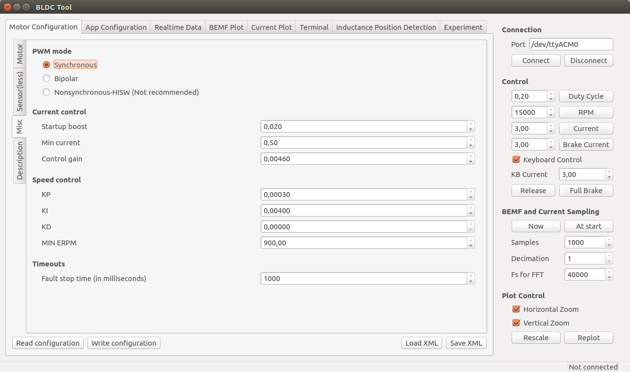
- PWM mode
- Synchronous is recommended and the best choice for a majority of all motors. If you have some weird motor, Bipolar could work better, but it probably won’t. Nonsynchronous is only for experimentation and can kill the ESC if you are unlucky.
- Current control
- Startup boost is the minimum duty cycle to use when using current control. If the motor is to weak when you are just starting, you can increase this parameter a bit until it feels right. The range is 0.0 to 1.0, where 1.0 is full throttle (which you shouldn’t use.). A sane range is up to 0.15 or so.
- Min current is the minimum allowed current. There should be no reason to change this, so leave it at the default value.
- Control gain is the gain used by the current controller. Increasing it makes the current response faster, but also increases the risk of getting an unstable system where the ESC can get damaged. Only change this if you know what you are doing.
- Speed control
- The PID parameters for the speed controller. Only change them if you know what you are doing.
- Timeouts
- Fault stop time is the amount of milliseconds that the ESC should be completely switched of when a fault code arises. After that time, it will switch on and try to listen for commands again.
Application Configuration
First, click “Read configuration” to get the current configuration from the ESC. After that, select which application to use and configure that application.

- Controller ID is the ID of this VESC. If multiple VESCs are connected over CAN-bus, they must have different IDs.
- Send status over CAN has to be enabled to make other VESCs aware of this VESC and some of its current state. It should be enabled for all slave VESCs when connecting multiple VESCs over CAN-bus.
- Changing application requires a reboot. There is a button for that. After a reboot, you have to click connect again.
- Timeout is the amount of milliseconds after which the motor should be shut off in case the control signal is missing.
- “Brake current to use…” can be set to make the motor brake with a certain current when a timeout occurs instead of just releasing it.
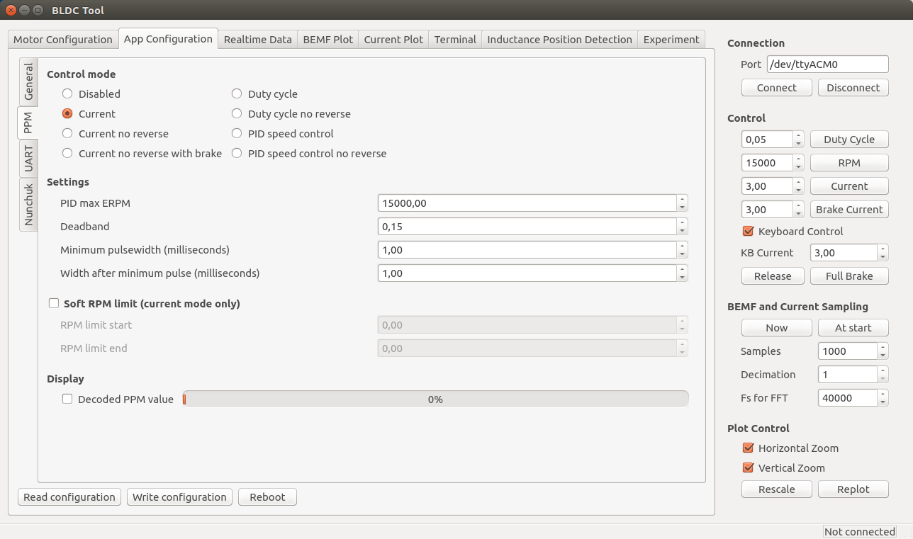
PPM
The signal that a normal RC receiver outputs is a PPM signal, so this can be used when connecting an RC receiver to the servo port.
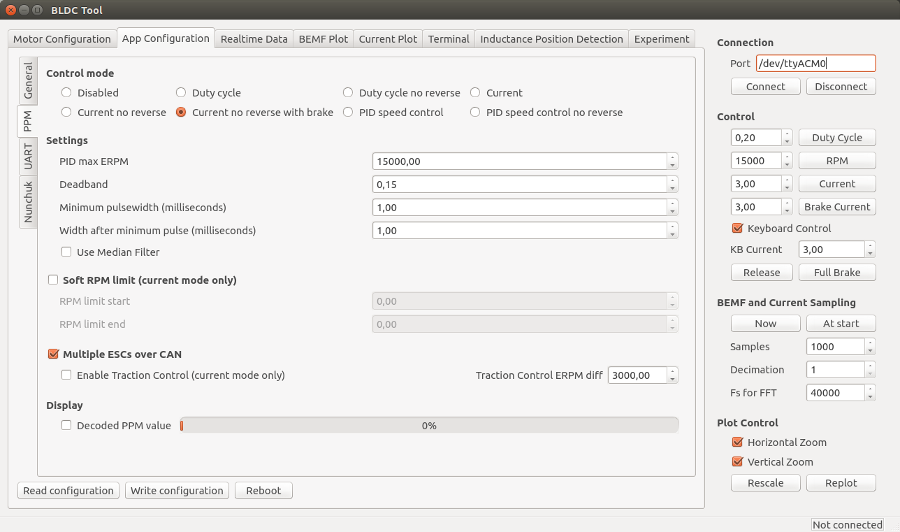
- Control mode
- Disabled: Nothing at all, motor is off.
- Current: Torque control. This is what I prefer since it feels most natural. I haven’t seen hobby ESCs that have current control.
- Current no reverse: Save as above, but no reverse function. Note that centring the now will give half throttle.
- Current no reverse with brake: No reverse, but centre is zero torque. Reversing will brake, but not change motor direction.
- Duty cycle: Duty cycle or voltage control. What most hobby ESCs use.
- PID speed control: The throttle command is intepreted as a speed set command and closed-loop control is used to maintain that speed. “PID max ERPM” sets what max throttle should be interpreted as.
- Settings
- Deadband: how much span in the centre of the throttle should be ignored.
- Minimum and maximum pulsewidth: The timing interpretation of the PPM signal can be adjusted in case your receiver doesn’t follow the specification or it you have some other reason to change it. Setting “Control mode” to “Disabled” and ticking display decoded PPM value is useful when adjusting these.
- Use Median Filter enables a filter that is very useful when there are glitches on the PPM signal. If you have a quadcopter application, you should disable the filter and make sure that there are no glitches since a filter introduces some delay.
- Soft RPM limit.
- Speed limit that can be used in current control mode. Setting the start and end limits a bit apart will result in a soft torque decay when approaching the speed limit.
- Multiple ESCs over CAN can be enabled to connect several VESCs over CAN bus. All VESCs must have different Controller ID and the slave VESCs must have Send status over CAN enabled (see the general tab under app configuration). The slave VESCs don’t need to have any application enabled since they will just be listening for CAN commands. Traction control can also be enabled, which reduces the torque on motors that spin faster than the slowest motor proportional to their speed difference. To connect VESCs over CAN-bus, connect the CANH and CANL signals between them. DO NOT connect 5v and GND because that is likely to cause ground loops which can reset and/or kill the VESCs.
Nunchuk
The Nyko Kama wireless nunchuk can also be used to control the ESC. Note that not all nunchuks for the nintendo wii will work, because they slightly differently.
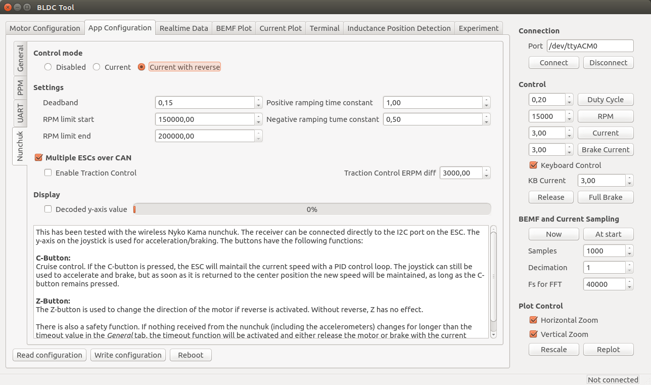
- Control mode
- Disabled or current control with or without reverse. If reverse is used, the Z button is used to toggle a direction change.
- Settings
- Deadband: The span in the centre of the throttle that should be ignored.
- RPM limits: Limit the electrical RPM of the motor. The start value is the point where the torque should start decreasing and the end value is the point where the output will be switched off. Setting them slightly apart will give a soft RPM limit. Setting them very high will disable the RPM limit.
- Ramping time constants: How fast the throttle command should be followed, in seconds.
- Multiple ESCs over CAN can be enabled to connect several VESCs over CAN bus. All VESCs must have different Controller ID and the slave VESCs must have Send status over CAN enabled (see the general tab under app configuration). The slave VESCs don’t need to have any application enabled since they will just be listening for CAN commands. Traction control can also be enabled, which reduces the torque on motors that spin faster than the slowest motor proportional to their speed difference. To connect VESCs over CAN-bus, connect the CANH and CANL signals between them. DO NOT connect 5v and GND because that is likely to cause ground loops which can reset and/or kill the VESCs.
A video where I test this:
Realtime Data Display
Use the “Realtime Data” tab to display realtime information from the ESC. Make sure that the “Activate sampling” box is checked.
Common Problems and Solutions
As I encounter different problems, I will put them here together with possible solutions for reference.
Uploading the firmware does not work.
- Make sure that you have followed all steps in the tutorial, including adding udev rules to access the programmer without being root.
- Don’t use a too long cable for the SWD connector.
- Make sure that you have a working programmer. I got one from ebay that didn’t work at all and one that died quickly. Otherwise they have been reliable though.
A DRV8302 fault code appears as soon as the motor starts.
- Make sure that R16 is not mounted (see the comment in the schematic).
Connecting to VESC via BLDC Tool does not work.
- Run dmesg to see which ttyACMx port gets assigned to VESC when plugging in the mini-usb cable.
- Make sure that the mini-usb cable is plugged in and that power is connected to VESC. Connecting BLDC Tool is not done via the SWD programmer, but via the mini-usb port.
- If you are using a different usb-connector than the one from the BOM, make sure that the order of the pins is correct. The connector in the BOM is upside-down, so a connector that isn’t will have all the pins mirrored.
My motor is not running properly.
- Make sure that you have configured VESC for your motor as described above. VESC is not plug-and-play and needs an individual configuration for each motor. Without the configuration, the motor will run poorly or not at all. Read the instructions carefully.
Is there a way to “boost” the startup of my motor when using current control?
- Yes, the Startup boost option under Motor Configuration > Misc tab in BLDC Tool can be adjusted as described above.
Update: I have ordered assembled VESCs, some of them are for sale
Update about this update: There are no assembled ESCs left. However, If you are interested in assembled VESCs you can still send me an email as described below so that I can put you on my extra list. If someone changes their mind or if there are other problems, I can send you VESCs that get left.
I have ordered 100 assembled VESCs and they will arrive this or next week. I don’t need all of them, so I will sell some of them for 115€ + shipping. Worldwide shipping with tracking is 20€ per order (which can contain more than one VESC). Shipping within Sweden is less expensive and I will update this post as soon as I know the price. You can contact me by email if you are interested (benjamin at vedder.se). Tell me how many VESCs you’d like and your address, and I will reply with an email that confirms that I have put you in my list. Later, when I have figured out how to accept payments, I will send another email with information about how to do that. As soon as I receive your payment, I will ship the VESC(s) to you and send an email with tracking information
I will update this information in the coming days, so make sure to check if there are updates.

Hello sir when i open the schematic file it asks me for BLDC_4-rescue and special library.. where can i found these?
hello sir please answer
Hi Benjamin,
I am currently working on a brushless controler with a design similar to yours (STM32 and DRV8302) but with smaller transistor (20A/30V).
I have the same issue you have described in this topic : https://e2e.ti.com/support/applications/motor_drivers/f/38/t/227363
(When the motor start rotating, i have random low pulse on the fault signal (not latched) and when i look GVDD, PVDD, or DVDD the voltage are in the range specified in the datasheet, the GND pin of the DRV is soldered, and i connect power and signal ground in a single point)
In this topic you talk about adding inductor but in the last version of the controler you don’t use it so how did you fix the issue ???
Thanks in advance for your answer ! and congratulation for your work !
Regards,
Arnaud LEBRUN
Hi,
This was due to bad routing on one of my old PCBs. I thing the AVDD capacitor in the DRV had too long traces in my case, but there can be other things that cause the same problem. Have a close look at your routing.
Hi,
It was what i suspected too and indeed with a new layout the issues seems fixed. I improve a lot of stuff so i don’t know where was the issue. But I did not change the way i connect the AVDD capacitor(was already realy short track) so i guess it was something else…
Thank you for your repply,
Regards,
Arnaud
Rather than build, I planned to order one of your boards from one of the online vendors that has sprung up: enertion, ollin, jacobloy, etc.
Can you confirm who you are actively receiving financial support from?
I didn’t want to support a vendor that was not helping your efforts. Thanks again for the continued development of this project.
Sorry for the late reply. From enertion I got a space cell once and ollin gives me a percentage for each board he sells. The best soldering and assembly quality I have seen is from ollin boards. He does a very good job with the assembly.
Hello Benjamin,
what’s the intended purpose of the TVS Diode?
Best regards,
Michael
hi,
It is to protect against voltage spikes on the 5V net. It has saved a few components for me already.
Spikes from the switching regulator? Or do you connect a 5V supply from outside? Do you remember which components died when the TVS wasn’t there?
Hello,
I am designing a custom brushless and non-sensored DC motor for specific application. The motor has 12 teeth and 10 magnets and should run on 36V and 500W power. It is winded with dLRK and connected as star. I got hold of couple of VESC’s and I really like the design and access to the parameters. The only problem is that I don’t seem to be able to configure VESC so that it could run the motor smoothly. Motor should run with about 1200 RPM max and I was able to get it detect integration limit and BEMF coupling only with few runs. The results I got were like these: Amps 12, RP 600, Low duty 0.36 gave 980 integration limit and 620 BEMF coupling. The other two successful detections gave these results:
14/640/0.3 = 910 / 526
14/630/0.3 = 895 / 881
Still the initial spin is very jerky and and smooth at all. Low RPM revolving is more or less OK when running the detection, but keyboard control is not able to turn the engine at all even if I set the detected settings. I am quite noob with this motor stuff and I have no good idea how to debug the settings. My question is that should it first of all work with such an engine since it is a bit different from standard hobby engine? Inertia of the rotor is also rather big since the rotor weights roughly 1.5 kg. I was also wondering about the PID control parameters that is there any point changing those? And finally I noticed that the current firmware is 2.4 and the VESC that I have has 1.14 FW, are there any major changes in the latest one that might help me? Thanks for publishing this wonderful project.
Cheers,
Kari
Hi Kari,
An integrator limit of 900 sounds very high, so that is most likely wrong.
FW 2.4 is a huge update with full FOC support, so you can give that a try. There is also auto-detection of all motor parameters. I will write more about that and make a video tutorial soon.
/Benjamin
Just a late update. The root cause was one phase crossing from the other motor on two motor configuration. So in essence the 3 phase motor was running with just two phases. No wonder it was “very jerky”… VESC works like a dream now
Kari, I seem to be having a similar issue. How did you confirm that the VESC was outputting in three phases?
Hi Benjamin.
I think there is a bug in the file called mcpwm_foc.c line 243, which says:
TIM_OCInitStructure.TIM_OutputNState = TIM_OutputState_Enable;
This should be:
TIM_OCInitStructure.TIM_OutputNState = TIM_OutputNState_Enable;
I can’t figure out how your code works without it – maybe you don’t use the complementary pwm, or ?
– And also in line 262, which says:
TIM_BDTRInitStructure.TIM_OSSIState = TIM_OSSRState_Enable;
should be:
TIM_BDTRInitStructure.TIM_OSSIState = TIM_OSSIState_Enable;
However, this seems to have no effect.
Pingback: Project Spotlight: VESC Open Source ESC « OpenFET
Hi Benjamin, I have assembled some 4.10 PCBs , but the motor has no any respond in detection procedure, also the temperature figure shows 450c around. I think there are something wrong for hardware version. Can you please explain how to select hardware version in conf_general.h, thanks!
Regards,
Adam
And in the bldc-tool’s terminal shows fault “FAULT_CODE_OVER_TEMP_FET”
I’m sorry Benjamin, forget it, the problem come from the temp resistor, the stupid supplier sent me wrong one. anyway, it’s working fine. Thank you!
Hi Benjamin,i have read you code,but i have some question about that.
conf->sl_bemf_coupling_k 600
conf->sl_cycle_int_limit 62
how do you know the num?how to calculate it?
thanks!!
The bldc-tool will automatically detect these parameters, see the videos. Also in general, you might want to use the forums instead for such support, either http://vedder.se/forums/ or at endless-sphere at https://endless-sphere.com/forums/viewforum.php?f=35&sid=6f121a4292b5b387b5623dcc0175e764
Hello benjamin, i have a question.
I can’t see any calibration configuration for the motors. What do you think about implemented in?
Regards
Hi Benjamin,
First of all, this whole project is really amazing ! Its first purpose was to control your skateboard but you can basically do anything you want with it ^^.
I got some trouble trying to install the whole toolchain. When I’m executing your summon-arm-toolchain, I get the following the first I ran it :
“The ft2232 driver is deprecated, use –enable-ftdi to build its replacement, or force the old driver with –enable-legacy-ft2232_libftdi”
So I tried what the terminal suggested me then I got this :
–enable-legacy-ft2232_libftdi : commande introuvable
–enable-usb_blaster_libftdi : commande introuvable
(commande introuvable in french means not found command or something equivalent in english).
What can I do ?
I actually solved the problem. The only thing I did was that I typed the “./configure” thing related to OpenOCD directly in the terminal and it worked !
Thanks btw !
hello benjamin,
i would be glad if you could help me out in this,, after make upload command in bootloader i am getting error as follows :-
“This adapter doesn’t support configurable speed Error: read version failed in procedure ‘transport’ ** OpenOCD init Failed ** shutdown command invoked…””
i am using SWD discovery board and because of this error it not showing my motor connected..
please help me out with a possible way to overcome this error.
will be waiting for your reply to the soonest..
thankyou
please give me suggestion benjamin
i have the same problem, tried everyting, but still not work… 🙁
If you have the st-link connected correctly you may want to check for bridged legs on the stm32 chip. The VESC should also give you a blue led when you connect the stlink/programmer.
I’m also having this issue 🙁 Anyone got any idea whats wrong?
Use shorter wiring on the programmer. I had the same issue using about 12″ wiring on the jst connector. Shortened it to 6″ and never had the problem again.
HI ,
can i use the VESC in PMSM motor?
Do you have any problems with these observer in your FOC?
I have a similar implementation, but it has a 180° uncertainty at zero rpm so it can start in both directions randomly. Or do you use a ramp for the startup?
Hey Benjamin,
I’m trying to write a custom ADC app. I followed your instructions but got a make error ( (float)ADC_Value[ADC_IND_EXT]; undefined etc ). Should we use mc_interface.h rather than mcpwm.h?
What are your long term plans for the VESC now that you’ve implemented FOC?
Hi Benjamin,
Your project is absolutely fantastic! It can see that you’re in it had to spend a lot of time experimenting.
I have a few questions for Thy project:
– Do you think it would be possible to use Your VESC for a project similar to the Segway? I do not understand yet exactly all settings, but you can use VESC motor drive in both directions with break?
– Have you tried VESC at some hub bike motor?
– It would be possible to use OptiMOS IPT007N06N – in my opinion still has better specs (less resistance R (DS))?
Thank you in advance for your response and I wish you every success in the further development.
Hi,
I’m trying to made a Segway with two VESC’s now. It has two 1,5 kW hub motors from e-bike, arduino mega 2560 with control algorithm and 12S 10,4 Ah LiPoly battery.
I think that I get some valuable informations in a month, when I will make first tests.
If you are still interested I can tell you then if it is possible to make a Segway with VESC’s.
I’ve done first tests of my Segway-like vehicle with two VESC’s. The main answer is: yes, it is possible!!! VESC’s are working great with 1,5 kW hub motors and FOC. Motors are very silent in comparision to BLDC mode. Of course you have to run in sensored mode. With mass of vehicle around 50 kg and me around 70 kg, forces are really huge and sensorless mode isn’t efficient. VESC’s are connected with arduino with PPM signal. I’m running in current mode and breaking in both directions isn’t necessary. If you have proper control algorithm, it works great in standard VESC configuration, without any changes. The main problem is high voltage and peak current of batteries. You have to mount soft-start if you don’t want to kill VESC’s. Vedder’s anti-spark switch with 2Mohm resistor and VESC’s 2200uF capacitors deals with that very well 🙂
Hi Benjamin,
I finally got the debugging to work on the VESC. FYI, I used a SEGGER J-LINK PRO to make it work, but I still don’t get it with a STLINK-V2.
Btw I have another problem. When I try to connect the board using the usb shield, I get no answer from the computer. I used both lsusb and dmesg but nothing seems to happen when I plug the usb in (I even tried on Windows and with another computer). How did you handle the USB connection in this project ? Did you have to set something in the ChibiOS configuration or during the STM32 initialization ? Or is it supposed to be “plug and play”, either you load the software on the board or not ?
I hope you can provide me some help as I still cannot do anything with the VESC…
Thanks in advance !
Hi Marcel, are you saying that, to debug the VESC (for example in eclipse and with on-chip-debugging) a normal STLINK-V2 does not work?
I need to develop some code and debug it .
I still have to figure out how to debug within eclipse only (no OCD). Could you help me
Hi,
I can see a coil inductor on your assembled pcb but I can’t seem to find one in the wiring diagram. What is it for and where is it in the diagramm? Thank you!
It is mentioned in the BOM as Power Inductor – L1 (652-SDR0805-220ML).
Sorry, found it myself.
Mayday:
After hitting: “Start detection” the Motor “slapped” once hardly in one direction. After that the motor was dead. So not the motor was damaged but I thing something is damaged on the power site of the bldc. Processor etc. is still runniing. But the motor shows no reaction on bldc-tool control. Tried it also with another motor. No chance. Also a new firmware-update didn’t help.
Can anybody help me to find the problem? I don’t know how to examin the MOSFET’s
What hardware version did you build and did you upload the correct firmware for that version? If you uploaded the wrong firmware version onto v4.10/4.11 HW it is possible that you burned the trace next to R29 and burned your drv8302.
A bit tricky really on a board because if the FETs are dead then probably burnt through like a fuse. Usually though only one top get and one bottom get are burned through – the others are ok. Sometimes they are cracked. You can measure the resistance between drain and source – will be open circuit; the gate to drain and maybe gate to source probably short circuit. The intrinsic diode S-D is probably also open circuit and you casually measure this with a diode tester from source to drain.
Pingback: Adding Position Control To An Open Source Brushless Motor Driver | Hackaday
Pingback: Adding Position Control To An Open Source Brushless Motor Driver | Ad Pub
Pingback: Adding Position Control To An Open Source Brushless Motor Driver | Máy Điện
Hello everybody,
I have some of PCB ver. 4.11 (8 pieces), you can see
http://www.ebay.com/itm/PCB-for-3-phase-BLDC-brushless-motor-controller-board-VESC-open-source-ESC-/111912433806?
Milan
Hi friends, I’m selling my last items for VESC board assembly. I don’t have more time to assemble due to work and university so its its your time to rock VESC boards. You will be happy with this suppluie and money is welcomefor home sustain. : )
Please check out http://goo.gl/rWNfr7
High grade High quality best finishing shiny four layer’s PCB.
Plus components to assemble 5 boards, all original genuine direct from factory. Best genuine IRF MOSFETS ultra low resistence very high current.
Please contact if need.
Salut
Hello,
Could you give some information about regenerative brake system?
The energy goes inside the input capacitor (connected to the battery pack)?
I suppose that this break system could be adapted (limitation of negative acceleration for don’t block the wheel connected to the motor)?
Is it directly use when the quick command is bellow than the current speed?
thank you for your job,
Arthur
I want to use this ESC for a 4-wheels driven mountain-board (BLDC sensorless).
With an other electronic board connect with CAN-bus to the 4 VESC, I will add some CAN command for ask temperatures, battery voltage, tachometer data, and set parameter as direction control.
Maybe I will try to apply the parameter of one VESC (read by my electronic board over CAN) to the other VESC (transmit with CAN).
Hi,
Is there any example code or communication specs for CAN bus control. I’d like to use embedded Linux platform to control and monitor VESC over SPI CAN bus controller. Alternative would be to use USB, but if monitoring data (voltage, wattage, rpm, etc.) can be monitored from CAN bus, it would be neat and more robust solution (I think…)
I’d appreciate it if you could point me the direction of some source code or similar that would have the communication specs defined.
Cheers,
Kari Kolehmainen
Did you ever figure this out? I have a similar application.
Pingback: II – L’électrique et électronique – Skate, longboard et mountainboard électrique DIY
Pingback: Das BLDC Tool unter Linux installieren… | roboshack
Hi Everyone,
I’m having an issue that I’m hoping you can shine some light on.
When I operate a motor at 12V, the fault pin is high; however, when I change the voltage to 12.4V, I get a strange value for the fault pin:
https://drive.google.com/file/d/0B5KTH8x5JsZBRzIxZ0dyMG1mUnM/view?usp=sharing
And subsequently, when I’m over 12.5V, I get the following:
https://drive.google.com/file/d/0B5KTH8x5JsZBZWxfNjF4NGNfWHM/view?usp=sharing
When I check the motor driver datasheet (DRV8302), I noticed that the fault pin needs to be pulled up. My PCB version 4.11 and isn’t pulled up.
Any ideas? Thanks.
Hello,
I have a little problem at controlling the VESC with an tennsy 3.1. I use the PPM input and the current control because I need the direction of the motor changed as fast as possible and PPM is the simplest way to control a ESC.
As PPM signal I tried to send an standard PPM Signal from 1ms to 2ms @50Hz and the zero point @1.5ms.
But the motors keep spinning at startup with the Firmware 1.12 and the actual GIT firmware (both tested) with hardware 4.7. I figured out that the zero Point (no motor spinning) is at 1.455ms instead of 1.5ms.
In the BLDC-tool only the min and max PPM signal length could be adjusted (these are on mine BLDC 1ms and 2ms).
I would suggest, that the zero PPM signal length could be adjusted also. I hope this is possible to integrate.
Thank you
Hello Benjamin,
I just wanna ask if you maybe know what dead time do you use on PWMs?
I am building similar ESC, and I have really big dead times, like 800ns.
What are yours, do you have it somewhere in the code?
Regards,
Jan
HI Benjamin, Is the 3 pin ppm connector for both servo ppm signals input as well as output, ie it can be used to read in a ppm input or send out a ppm output? it seems its just connected to PB5 which is just a GPIO so it can be configured as input or output. Right?
Hi,
Yes, you can use it for both. You have to enable servo output in conf_general.h and remove the low pass filter to use it as output.
Hi Benjamin,
Based on your design I have developed a slightly modified controller that i want to share with you. It uses 2 doublelayer PCBs connected by a 30pin 0.8 pitch Board2Board connector separating MOSFET’s and controller. I wanted to have an upgradeable FET stage and allowing easier cooling by positioning the FETs at the same component side.
https://www.dropbox.com/s/k203w9fqtyb2xgd/SDIM0005.JPG?dl=0
https://www.dropbox.com/s/x83b3asf1519tat/SDIM0006.JPG?dl=0
https://www.dropbox.com/s/qb1m01wwk3jb36s/SDIM0007.JPG?dl=0
The design is based on the F405RG and the DRV8301. I interchanged TIM1 and TIM8 and the respective PWM outputs to support an optional secondary CAN-interface (for redundancy issues).
For SW-development (most of it is trying to understand/adapt code) i use CooCox and J-Link.
Thank you for sharing all of your work with us Benjamin !
I’m quite new in all of that and the design is not fully tested/functional yet but will keep you informed.
Hey this is interesting do you have the schematics/layout files or any more info on this – did it work?
Thanks,
Rob
Hi Benjamin,
nice work, I really got some inspirations from your project.
One thing I don’t get till now in the H-bridge part: why is resistor R36 connected to the source of Q2 and not to the source of Q4?
Has it something to do with the current measurement in the half-bridge for phase 1 and 3?
Wouldn’t it be better to have a “symmetric” design for each half bridge?
Maybe you can enlighten me.
Hi, Benjamin. Great~~job~~!!!
Could I get Gerber file?
Is there any test tool for MS? link is not working~!
Hi, there is a new released DRV8305-Q1 it would be a nice improvment on this board. It allready has current sense amplifiers, more EMI protection and SPI interface. Also can go up 150degrees operation and automotive rating.
I click the start detection.but in the right it tells that bad detection reslut receive. what wrong with bad detection reslut receive?
Why I can not download the schematic of complete I’m really really to make a ESC of 32bit with supporting CAN bus and something else!!!!!! THANK YOU!!!!!!
Dear engineer,
does your esc load up batterie if the motors go into generator mode (easy said if you brake)?
Thanks for help!
Regards
Hi, I am currently working on a regenerative application which utilizes a 1KW BLDC motor rated at 48V. I intend to connect a 48v Lithium-ion based 48v 15Ah battery. Can I know how the board convert the BEMF to usable energy and is it able to regenarate at all speeds of the motor? Does it cut off when the speed is low? And does the regen have any negative effects on the battery?
Thanks for your time and patience to read my query.
Hi Benjamin,
I have a 8055 motor (80mm version of 6355 motor) with 6825 stator size 90kv 12N14P running as hubs (homemade) with around 12s and 45 battery feed amps. Can I run this motor with your VESC? I heard that there is higher tendency of frying the chips if VESC are ran with bigger motor sizes (larger than 63mm). Was planning to get v4.12 or wait for your v6.0. Is it possible to run these large motors? Any suggestions? Work or not, v4.12 or v6.0, plain bldc or foc? The community suggested that I ask for your opinion here, they are not so sure about it either. Thanks Ben! 🙂
Hi Benjamin,
First of all, this whole project is really amazing ! Thank you so much for sharing this with us!
Now i get some trouble trying to run the motor with the mode of duty cycle no reverse,it seems have brake,so my motor always very hot when i use it for several minutes? and occasionally reversal problem occurs when the motor start, How to get rid of the brakes ? thanks
Hi Benjamin,
As always thank you very much for sharing your amazing work !
We need to run with duty cycle no reverse mode for our multirotor UAV project, in order to get fastest dynamic response possible. We noticed that this mode has brake turned on, perhaps as a result the motor gets hot with loss of energy efficiency. we also get squeaking sound when turning throttle up and down very fast. Sometimes on startup the motor runs in reverse direction as well.
We noticed that when run with a motor designed for FOC, the performance is very good.
my questions are:
1. how do I turn off brake in duty cycle modes ?
2. is it necessary to use only PSMS motor designed for sinusoidal control ? we tried BLDC control for our motors, without much improvement.
Thank you for your help.
hello guys installing toll chain procedure is not working…. when i open the link for more information it is saying the page is private…
please help me i want to compile the firmware
If you need a VESC Repair Service in Europe, i can help you out. Check out my site http://www.lp-electronic.com/vesc-repair-service/
I’m located in Germany and can Repair VESC from all over Europe.
To what extent is the current VESC board design ready for energy recuperation by means of a supercapacitor? That is, to deal with higher frequencies of acceleration/deceleration cycles than what is best/possible for the batteries.
The sudo apt-add-repository command is failing with:
gpg: “tag:launchpad.net:2008:redacted” not a key ID: skipping
any ideas?
Installing at Ubuntu according the hints given does not seem to work
especially these commands don’t work.
qmake -qt=qt5
make
./BLDC_Tool
any update to the tutorial?
Fixed it
Installed a brand new 14.04 (Ubuntu 12 or 16 does not work ! ) and followed step by step:
https://roboshack.wordpress.com/2016/03/13/das-bldc-tool-unter-linux-installieren/
Hello
Is there any news about motor temperature monitoring. I am going to run it on e-bike mid motor, with integrated temperature sensor in the stator?
The sensor value is 70kohm at app. 20’c to be verified