Post updated 2016-01-22
About this project
I have made many updates to my custom motor controller recently and the old post is getting confusing with notes and updates, I decided to write a new post about it that hopefully is more clear, more complete and easier to follow. This might sound a bit ambitions, but my goal is to make the best ESC available. I really enjoy sharing knowledge, so I want to keep all the hardware and software open.
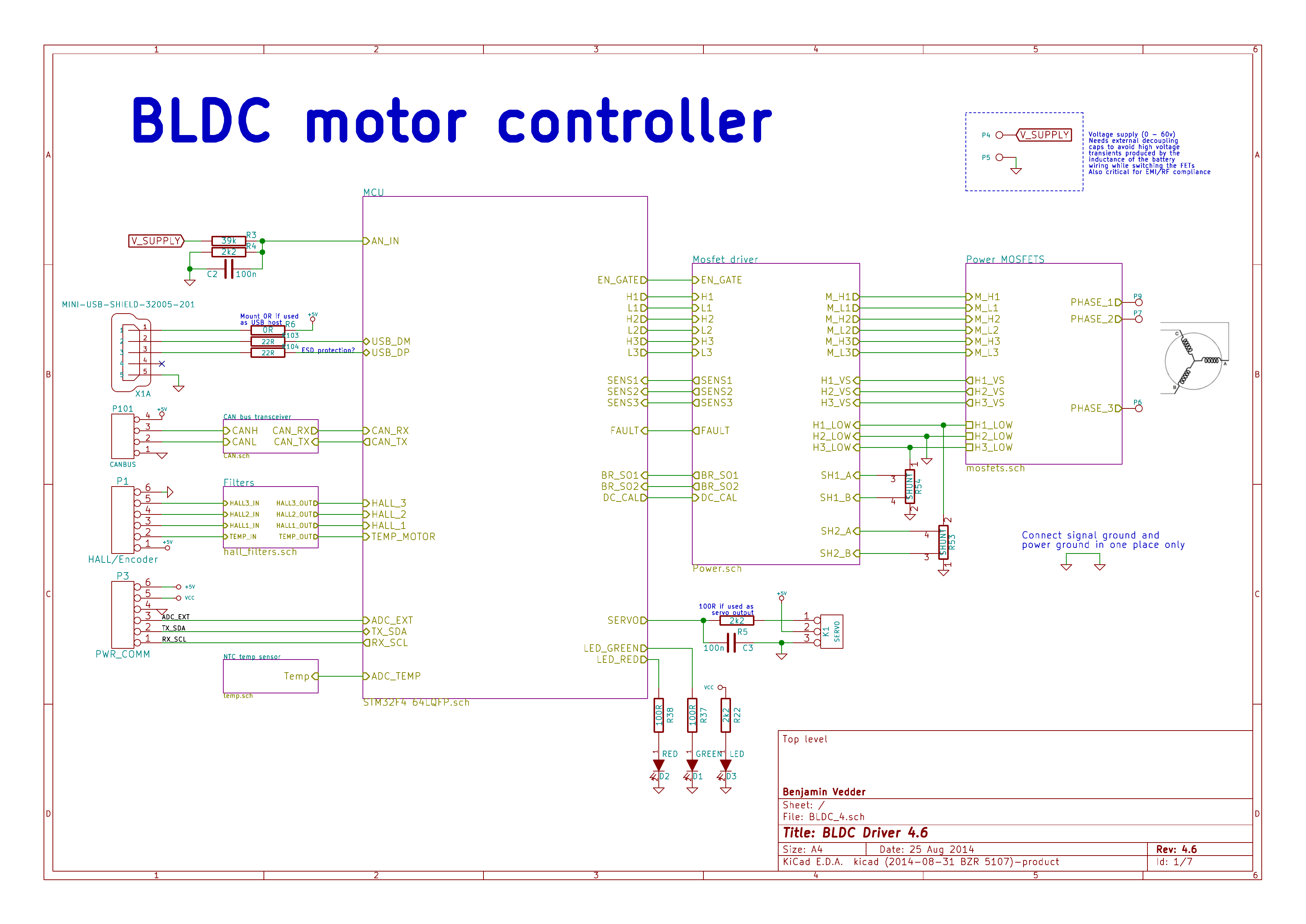
This is an overview of the schematic (download a complete PDF here):
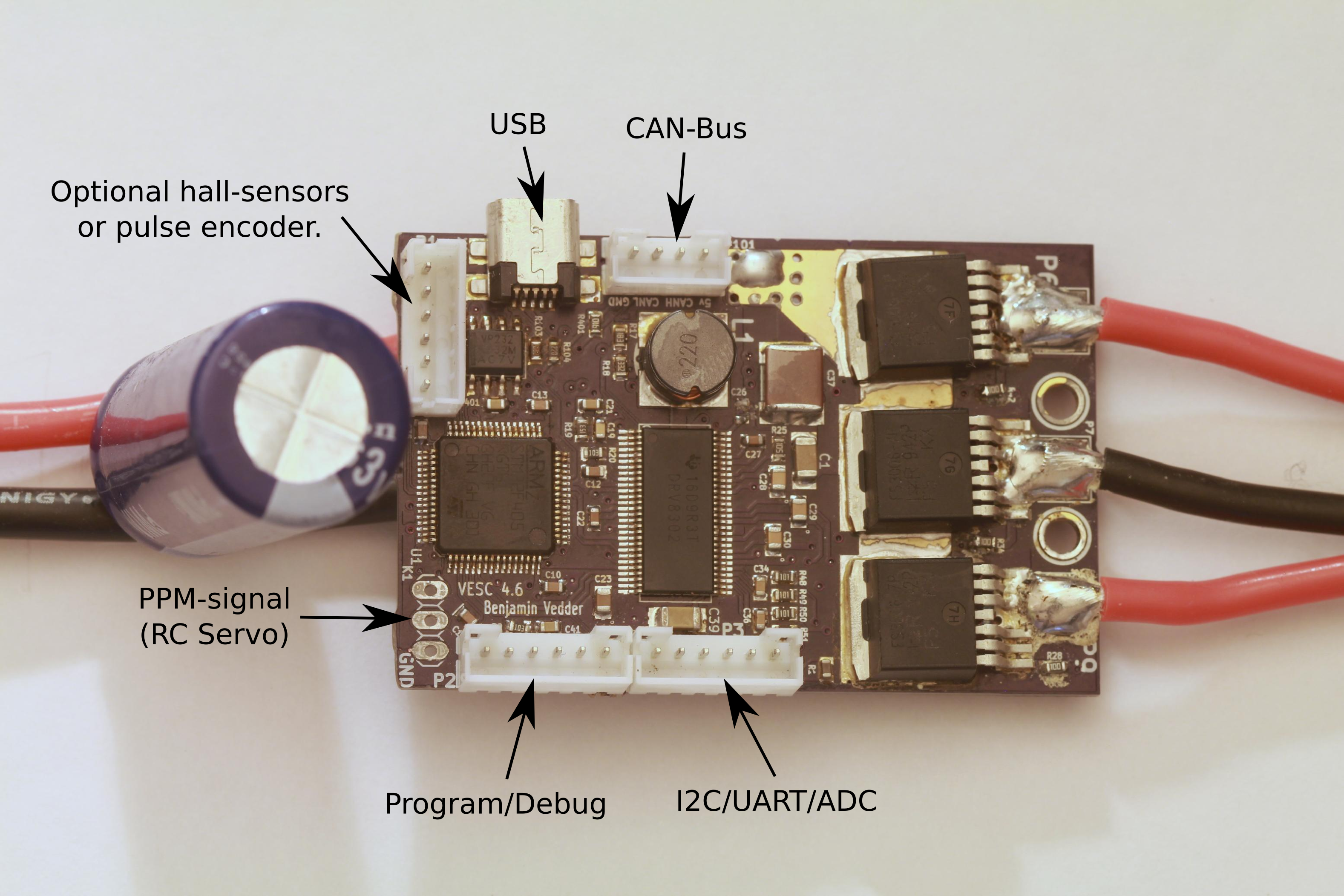
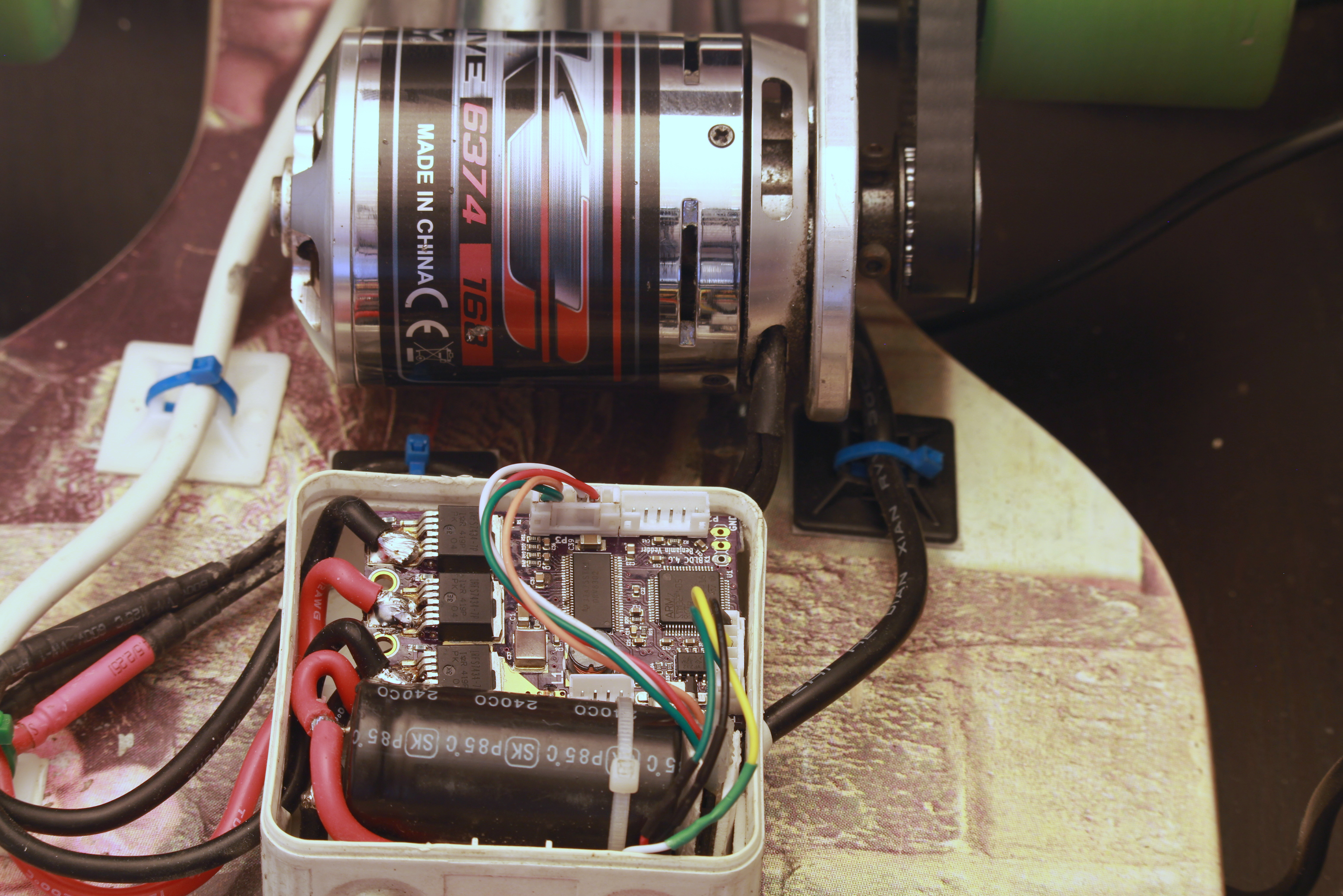
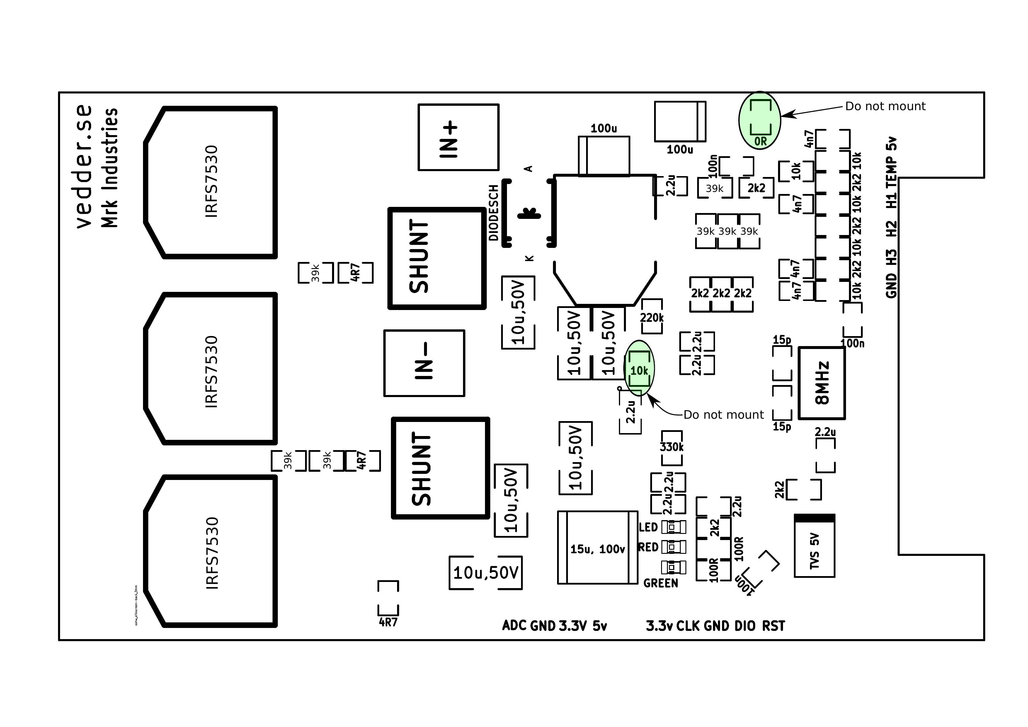
This is the front of the PCB:
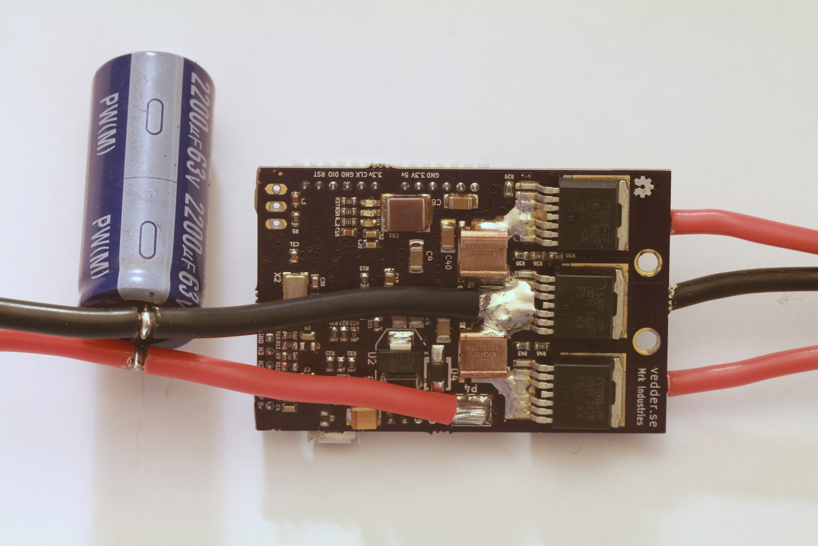
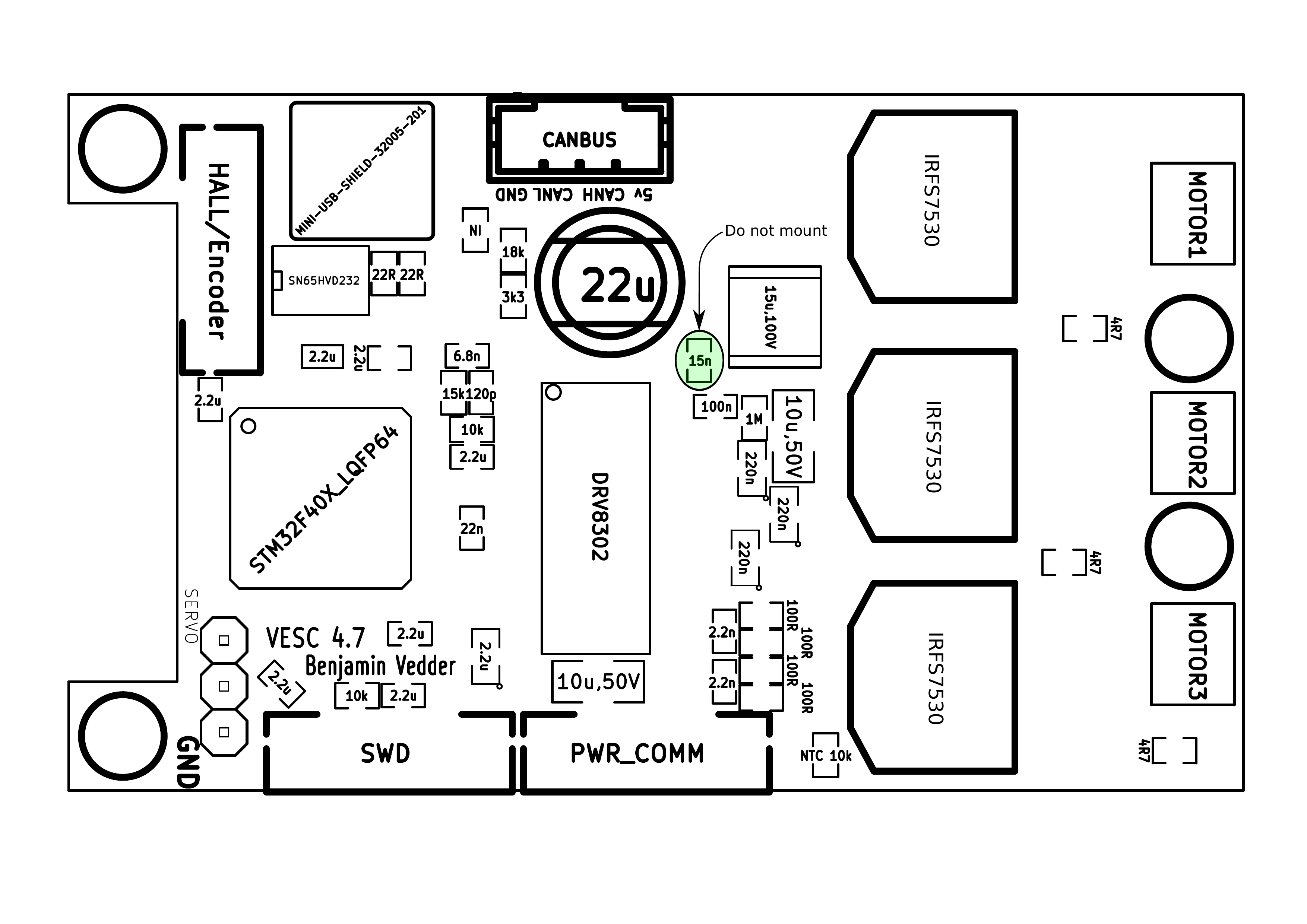
The back:
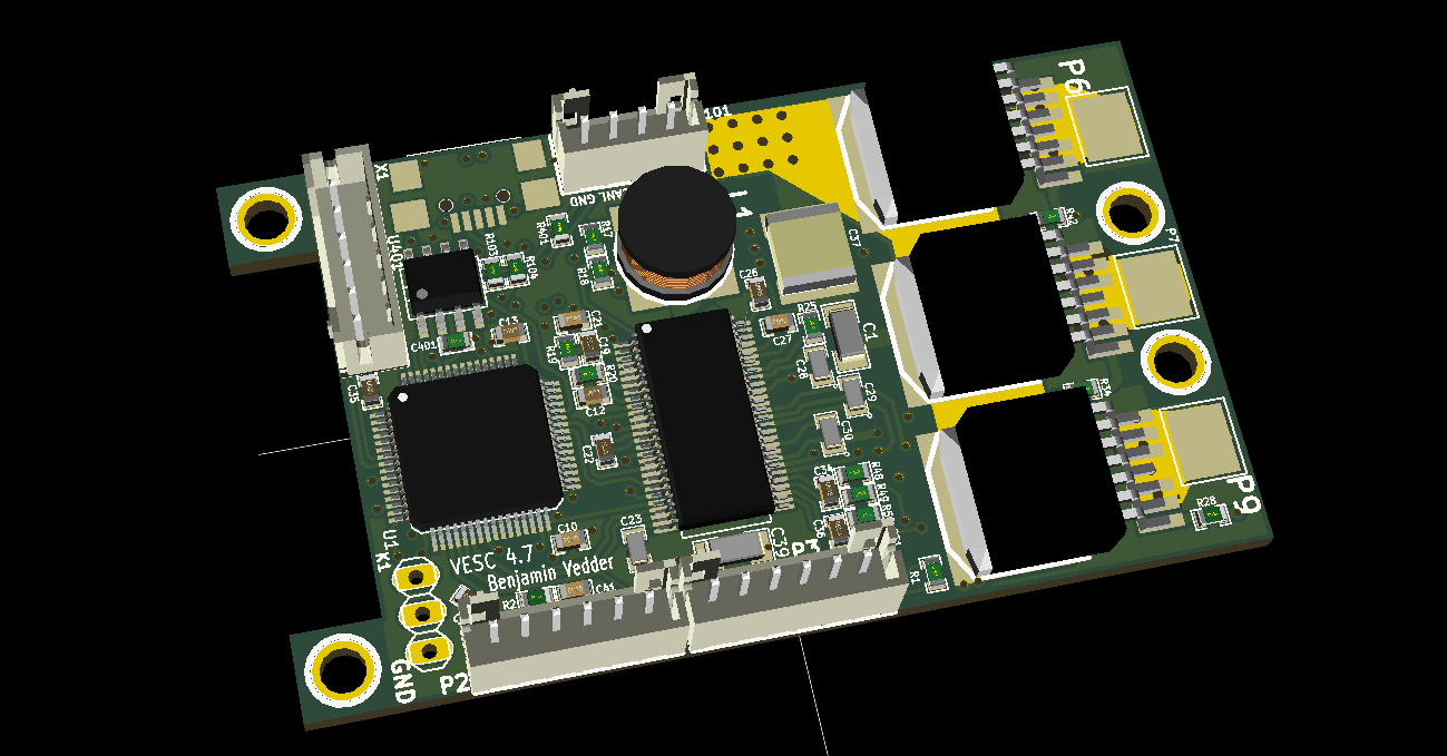
3D render from KiCad:
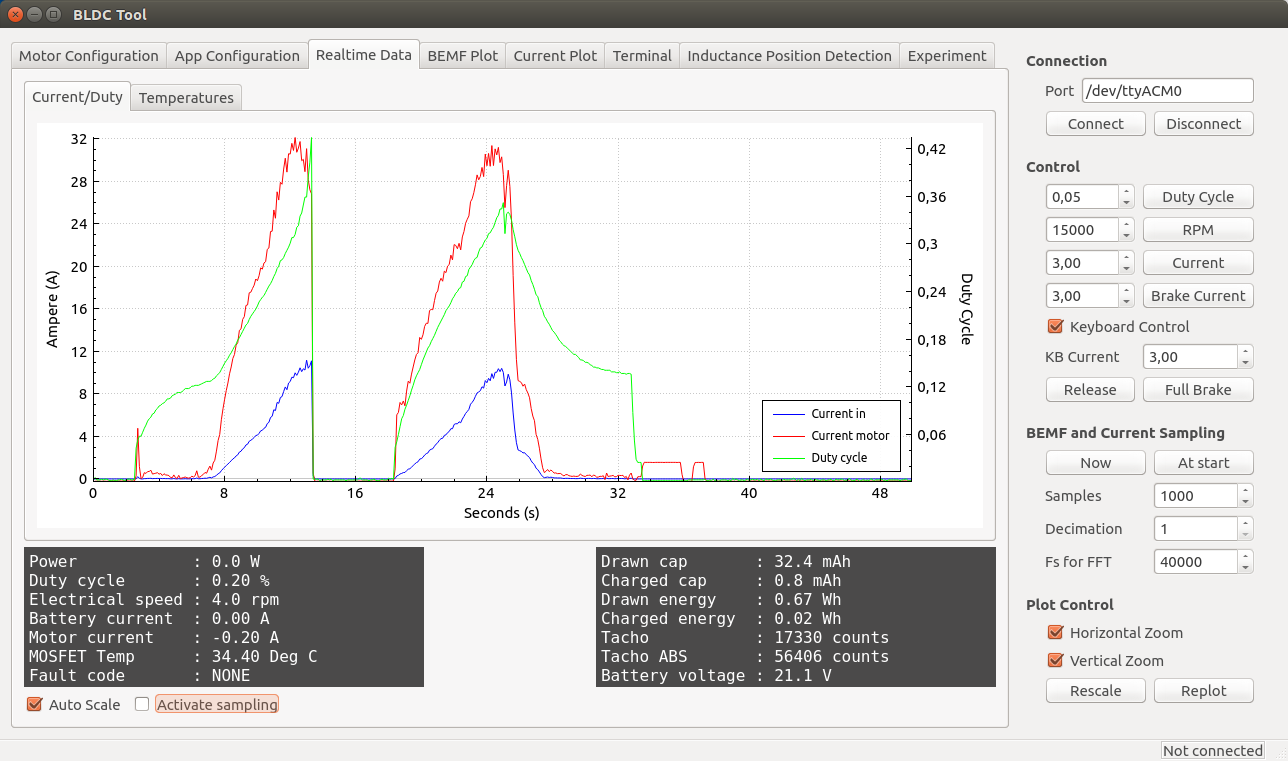
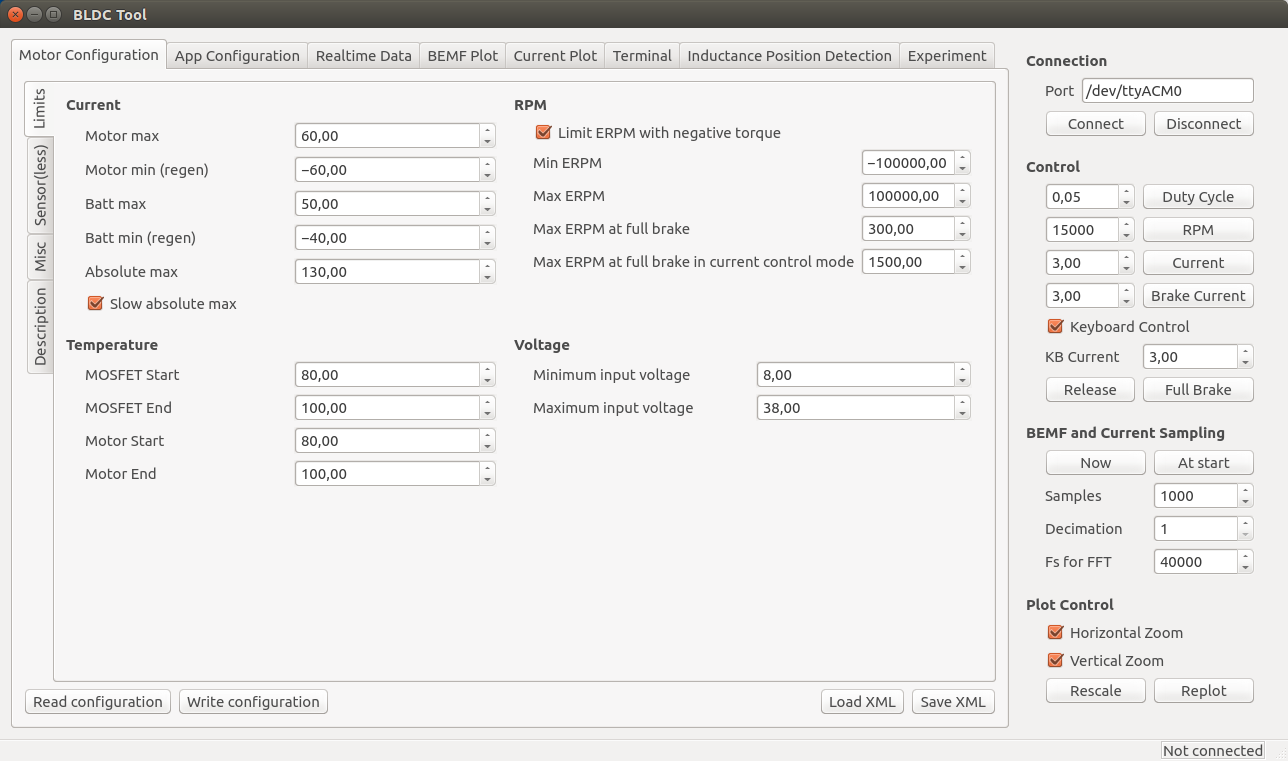
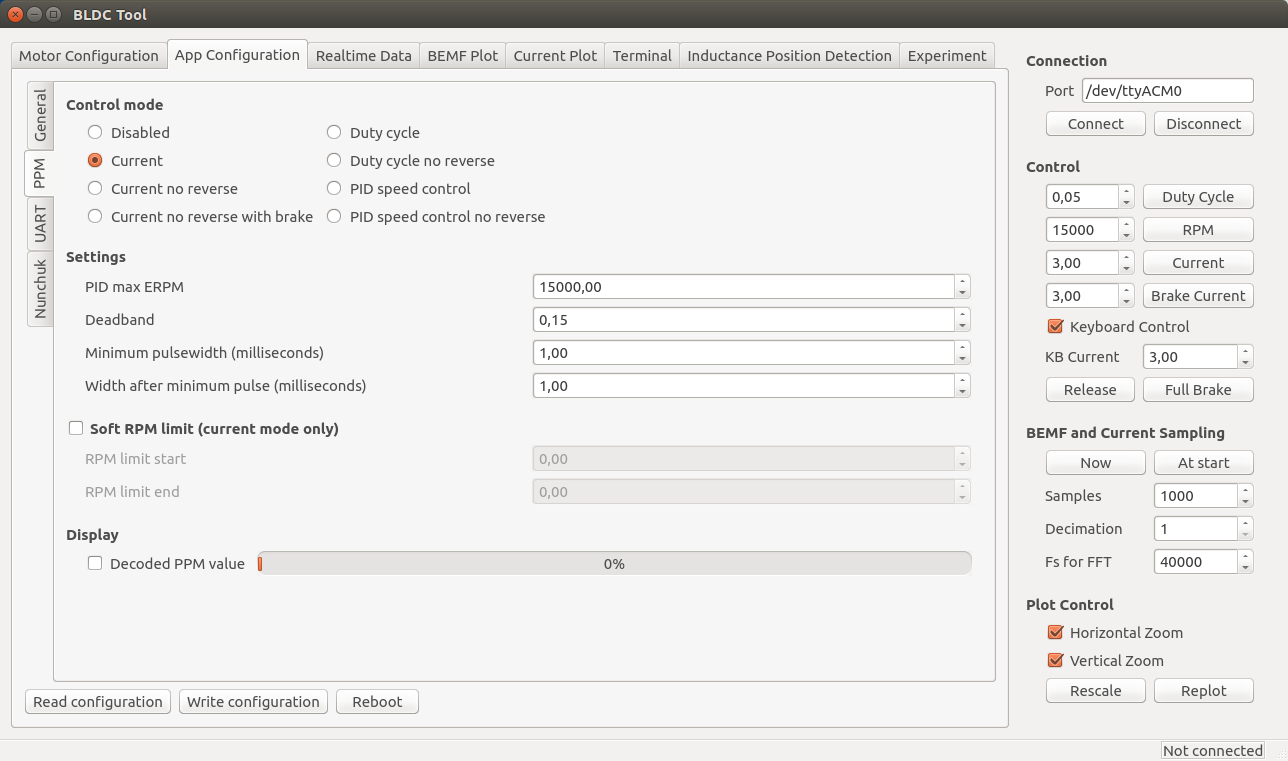
Some screenshots of the configuration GUI (BLDC Tool):
Resources
All files are on github to keep them up to date, so check these links on a regular basis:
- Hardware design
- Bill of materials
- Firmware
- Configuration GUI
- Video logger
- osx and windows builds of BLDC Tool, Video logger etc. by Jacob Bloy
Related posts
- Old post motor controller (just for reference)
- Video overlay logging
- Electric skateboard motor tutorial (KV, cells, etc.)
- Startup torque
- Hardware debugging
- Making a programmer
- Writing custom applications
- UART Communication
Forums
Because information about the VESC is scattered all over the internet and a lot of information is in email conversations with me, I have created a forum dedicated to the VESC here.
Live Chat
I have created an IRC channel on freenode where you can live chat with me and other users about VESC and my other projects. Feel free to join: http://webchat.freenode.net/?channels=vedder
Features
- The hardware and software is open source. Since there are plenty of CPU-resources left, the customization possibilities are almost endless.
- STM32F4 microcontroller.
- DRV8302 MOSFET driver / buck converter / current shunt amplifier.
- IRFS7530 MOEFETs (other FETs in the same package also fit).
- 5V 1A output for external electronics from the buck converter integrated on the DRV8302.
- Voltage: 8V – 60V (Safe for 3S to 12S LiPo).
- Current: Up to 240A for a couple of seconds or about 50A continuous depending on the temperature and air circulation around the PCB.
- Sensored and sensorless FOC wich auto-detection of all motor parameters is implemented since FW 2.3.
- Firmware based on ChibiOS/RT.
- PCB size: slightly less than 40mm x 60mm.
- Current and voltage measurement on all phases.
- Regenerative braking.
- DC motors are also supported.
- Sensored or sensorless operation.
- A GUI with lots of configuration parameters
- Adaptive PWM frequency to get as good ADC measurements as possible.
- RPM-based phase advance (or timing/field weakening).
- Good start-up torque in the sensorless mode (and obviously in the sensored mode as well).
- The motor is used as a tachometer, which is good for odometry on modified RC cars.
- Duty-cycle control, speed control or current control.
- Seamless 4-quadrant operation.
- Interface to control the motor: PPM signal (RC servo), analog, UART, I2C, USB or CAN-bus.
- Wireless wii nunchuk (Nyko Kama) control through the I2C port. This is convenient for electric skateboards.
- Consumed and regenerated amp-hour and watt-hour counting.
- Optional PPM signal output. Useful when e.g. controlling an RC car from a raspberry pi or an android device.
- The USB port uses the modem profile, so an Android device can be connected to the motor controller without rooting. Because of the servo output, the odometry and the extra ADC inputs (that can be used for sensors), this is perfect for modifying an RC car to be controlled from Android (or raspberry pi).
- Adjustable protection against
- Low input voltage
- High input voltage
- High motor current
- High input current
- High regenerative braking current (separate limits for the motor and the input)
- Rapid duty cycle changes (ramping)
- High RPM (separate limits for each direction).
- When the current limits are hit, a soft back-off strategy is used while the motor keeps running. If the current becomes way too high, the motor is switched off completely.
- The RPM limit also has a soft back-off strategy.
- Commutation works perfectly even when the speed of the motor changes rapidly. This is due to the fact that the magnetic flux is integrated after the zero crossing instead of adding a delay based on the previous speed.
- When the motor is rotating while the controller is off, the commutations and the direction are tracked. The duty-cycle to get the same speed is also calculated. This is to get a smooth start when the motor is already spinning.
- All of the hardware is ready for sensorless field-oriented control (FOC).
Writing the software is the remaining part. However, I’m not sure if FOC will have many benefits for low inductance high-speed motors besides running a bit quieter.Sensored and sensorless FOC is fully implemented since FW 2.3.
The is the ESC mounted on my electric longboard:
Sensorless startup and low-speed performance:
A short tutorial/demonstration on how to upload the firmware and get your motor running:
My electric longboard:
Video overlay logging (see a post about that here):
Hardware
The PCB is designed using KiCad. Have a look at the links under the Resources heading at the top of this page to find all files. Currently I have no assembled PCBs or kits to sell, but you can order bare PCBs from hackvana with these gerber files. Since hackvana got so many orders for my ESC, Mitch wrote a wiki page about how to order VESC boards from him. That makes it super easy to order the PCBs from him.
The components in the BOM can be ordered from mouser.com. Mouser numbers are included in the BOM as well. Make sure to order a bit extra of small capacitors and resistors in case you drop some of them and since the price doesn’t change much at all. Last I ordered, ordering 10 MOSFETs was cheaper than ordering 6 because there is a price break at 10, so have a look at the price breaks as well.
For assembling the PCBs, the following pictures are useful (the latest versions can be found on github):
Remember to put an electrolytic capacitor close to the ESC on the supply cable. How large it has to be depends on the length and inductance of the battery cables, but I usually use a 2200uF 63V capacitor.
Soldering Tips
This is the best tutorial I have seen so far. It really is as easy as it looks when done right.
- Flux is essential. Without flux, it won’t work. I use a flux pen.
- Lead-free solder is no good. It has more poisonous flux, requires more heat, gives lower quality and is difficult to handle. Don’t use lead-free solder.
- Use a flat, screwdriver-shaped tip. Don’t use a cone tip, because putting solder on the top of it is almost impossible.
- If you get bridges between smd pins, removing them is easy with a soldering wick.
- Make sure to get the alignment right for the microcontroller when soldering the first corner. If you solder multiple corners and the chip is misaligned, you have to use hot air and remove it, then clean the pads and start over.
Here is a video on the technique I use to solder the pad under the DRV8302:
I just put solder on the pad and use a hot air soldering station. Again, using leaded solder makes it easier. When soldering the DRV8302, I first solder the pad using hot air and then I solder the pins with a soldering iron. Notice that the pad under the DRV8302 must be connected for it to work, since it is the ground connection.

VESC Hardware by Benjamin Vedder is licensed under a Creative Commons Attribution-ShareAlike 4.0 International License.
Software Installation and Configuration Tutorial
This a brief tutorial on how to get everything running using a fresh install of Ubuntu 14.04. Here is a video where I do everything live to demonstrate that it isn’t that difficult. Please read all the instructions carefully to avoid most problems.
So let’s open up a terminal and get started…
Preparations
Install a toolchain to compile the firmware (for more details, have a look at this page):
sudo apt-get remove binutils-arm-none- eabi gcc-arm-none-eabi sudo add-apt-repository ppa:terry. guo/gcc- arm-embedded sudo apt-get update sudo apt-get install gcc-arm- none-eabi= 4.9.3.2015q3- 1trusty1
Install other dependencies
sudo apt-get install build-essential qt-sdk openocd git libudev-dev libqt5serialport5-dev
Add yourself to the dialout group to access the USB port of the ESC without being root:
sudo adduser $USER dialout
Uninstall modemmanager (unless you use it) to avoid a delay every time the ESC is plugged in to the USB port:
sudo apt-get remove modemmanager
Add udev rules to access the programmer without being root:
wget vedder.se/Temp/49-stlinkv2.rules
sudo mv 49-stlinkv2.rules /etc/udev/rules.d/
sudo reload udev
Log out and log back in. You should now be ready to compile the firmware, upload the firmware, compile BLDC Tool and run BLDC tool.
Download, Compile and Upload the Firmware
First, connect a programmer as described in this post. Then, download the latest firmware from github, compile and upload it:
mkdir BLDC
cd BLDC
git clone https://github.com/vedderb/bldc.git bldc-firmware
cd bldc-firmware
make upload
cd ..
Note: before running the make upload command, you should open conf_general.h and select which hardware version you are using. It is printed on the PCB. Also, 2015-01-22 I changed the voltage divider resistors to allow up to 60V to be measured by the ADC, so in that case you also have to override VIN_R1 to 39000.0 in conf_general.h.
Download, Compile and Upload the Bootloader
Again, connect a programmer as described in this post. Then, download the latest bootloader from github, compile and upload it:
mkdir BLDC
cd BLDC
git clone https://github.com/vedderb/bldc-bootloader.git bldc-bootloader
cd bldc-bootloader
make upload
cd ..
With the bootloader, BLDC Tool can be used to upgrade the firmware later.
Download, Compile and Start BLDC Tool
From the BLDC directory that you created in the previous step, type:
git clone https://github.com/vedderb/bldc-tool.git bldc-tool
cd bldc-tool
qmake -qt=qt5
make
./BLDC_Tool
You should see the following screen:
Connect the ESC to the USB port of your computer and click “Connect” in BLDC Tool. The lower right corner should now say “Connected”. If you have gotten this far, you should be ready to connect a motor and configure the ESC from BLDC Tool.
Note: If you have more than one usb-modem device in your computer (laptops often have built-in 3g modems), then you have to change ttyACM0 to the port of the ESC. To figure out which ttyACMx port the ESC got, open a terminal and type the following command right after plugging the USB cable in:
dmesg | tail
BLDC Tool can also be started by going to the bldc-tool directory with a file browser and double-clicking on “BLDC_Tool”.
Updating to the Latest Firmware
Updating to the latest firmware and the latest version of BLDC Tool is rather simple. From the bldc-firmware directory, type the following commands while the programming cable is connected to the ESC:
git pull
make upload
Note: Updating the firmware will delete the configuration of the ESC. To save it from BLDC Tool, use the “Read configuration” button and then “Save XML”. After updating the firmware, you can restore it with “Load XML” and “Write configuration”.
Also updating BLDC Tool is important and recommended at the same time as updating the firmware. In order to do that, go to the bldc-tool directory and type:
git pull
qmake
make
Now you have the latest version of the firmware and BLDC Tool. Remember to reconfigure the ESC after these changes.
Motor Configuration
Note: During the configuration, it is assumed that the USB cable is connected to the ESC and that the lower right corner of BLDC Tool says “Connected”.
The first thing to do in the “Motor Configuration” tab is to click “Read configuration” while the ESC is connected to get the current configuration. After that, click “Load XML” and look for a configuration that is the same as or similar to your motor in the “mc_configurations” folder included with BLDC Tool. If you find exactly your motor, you don’t have to change anything unless you want to tweak some parameters for your application.
Note: Even if you load an XML configuration file, use “Read configuration” first anyway because the XML might not contain all parameters. The missing parameters will become blank and can mess with things. Soon I will make sure that sane default parameters are loaded, but I haven’t done that yet.
Sensorless Motor Parameters
Since this ESC uses uncommon techniques to commutate the motor in order to get good low-speed performance without sensors, it is important to set correct motor-dependent parameters in the sensor(less) tab. Otherwise, the motor will run poorly or not at all.
This is what the Sensor(less) configuration page currently looks like (I will probably add more auto-detect options soon):
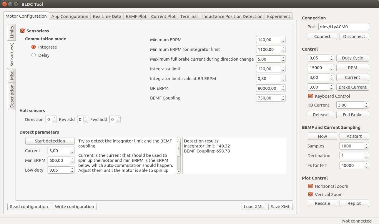
The important motor-dependent parameters are “Integrator limit” and “BEMF Coupling”, and they can be measured with the detection part. I will make a video showing this for several different motors soon, but until then you can try to follow these instructions:
- Connect the motor without any load and make sure that it can spin up freely.
- Make sure that no other input such as PPM is used. If it is, it will stop the motor immediately when the detection tries to start it and the detection will fail.
- Click the “Start detection” button. The motor should spin up, release throttle and then run slowly for a moment.
- If the motor doesn’t spin up properly, Adjust “Current” and “Min ERPM” until it does. In general, small motors should have lower current and higher ERPM and larger motors the other way around. Current usually is in the range 1A to 6A and min ERPM usually is in the range 300 to 1200.
- If spinning up works but running slowly afterwards doesn’t (the motor just stutters), try increasing “Low duty” to 0.1 or so. Increasing low duty will make it easier for the motor to run slowly during the test, but the result will become less accurate.
- Manually put the obtained values into the boxes. I usually round “integrator limit” down to the closest multiple of 5 and “BEMF Coupling” down to the closest multiple of 50. Having them slightly lower than the detection result is good in most cases, so that’s why I round them downwards like that. Getting these parameters perfectly right is not too critical though.
- The next parameters to adjust are “Min ERPM” and “Min ERPM for integrator limit”.
- What they should be depends on the application and is in most cases not too important, but in general lowering them will work better if the load has much inertia. I have Min ERPM around 200 and Min ERPM for integrator limit around 1000 for all my applications.
- You can probably keep the same parameters I have, but if you want to tweak your startup you can experiment with them.
- It is important that “Min ERPM” always is lower than “Max ERPM at full brake” and “Max ERPM at full brake in current control mode” on the “Limits” page.
- Commutation mode should always be “Integrate”.
- The other parameters are for RPM-based timing advance and some other things that aren’t necessary to adjust in the normal case, so I won’t explain them here yet.
For small low-inductance high-speed motors, the delay commutation mode can be used in case the integrate mode does not work. It does not require many parameters, just the minimum RPM which usually can be around 1500. I haven’t tested this mode much, but it is more or less how most hobby ESCs work (which is why it doesn’t require so many motor-specific parameters). Currently it does not support adjustable timing, but I will implement that in a few days since it is quite easy.
Phase advance (other terms: timing adjustment, field weakening)
To compensate for the current lagging behind the voltage at high speeds because of inductance or to get a bit higher top speed at the expense of some efficiency and torque, phase advance can be used. It is implemented in a speed-dependent way so that the motor gets more phase advance the faster it spins. It is implemented this way because having phase advance at low speeds does not give any improvements at all as far as I know, so the best way is to increase the effect as the motor increases its speed. BR ERPM is the electrical RPM of the motor at which the set phase advance is used, and Integrator limit scale at BR ERPM (will rename this option soon…) is the amount of phase advance to use. Setting it to 1.0 gives no phase advance and setting it to 0.0 gives 30 degrees (maximum) phase advance. The set phase advance will be mapped linearly between 0 ERPM and BR ERPM. If you don’t know what this is, you can leave the default options since it is not that important.
Motor
Current, temperature, RPM and voltage-limits can be configured depending on your application.
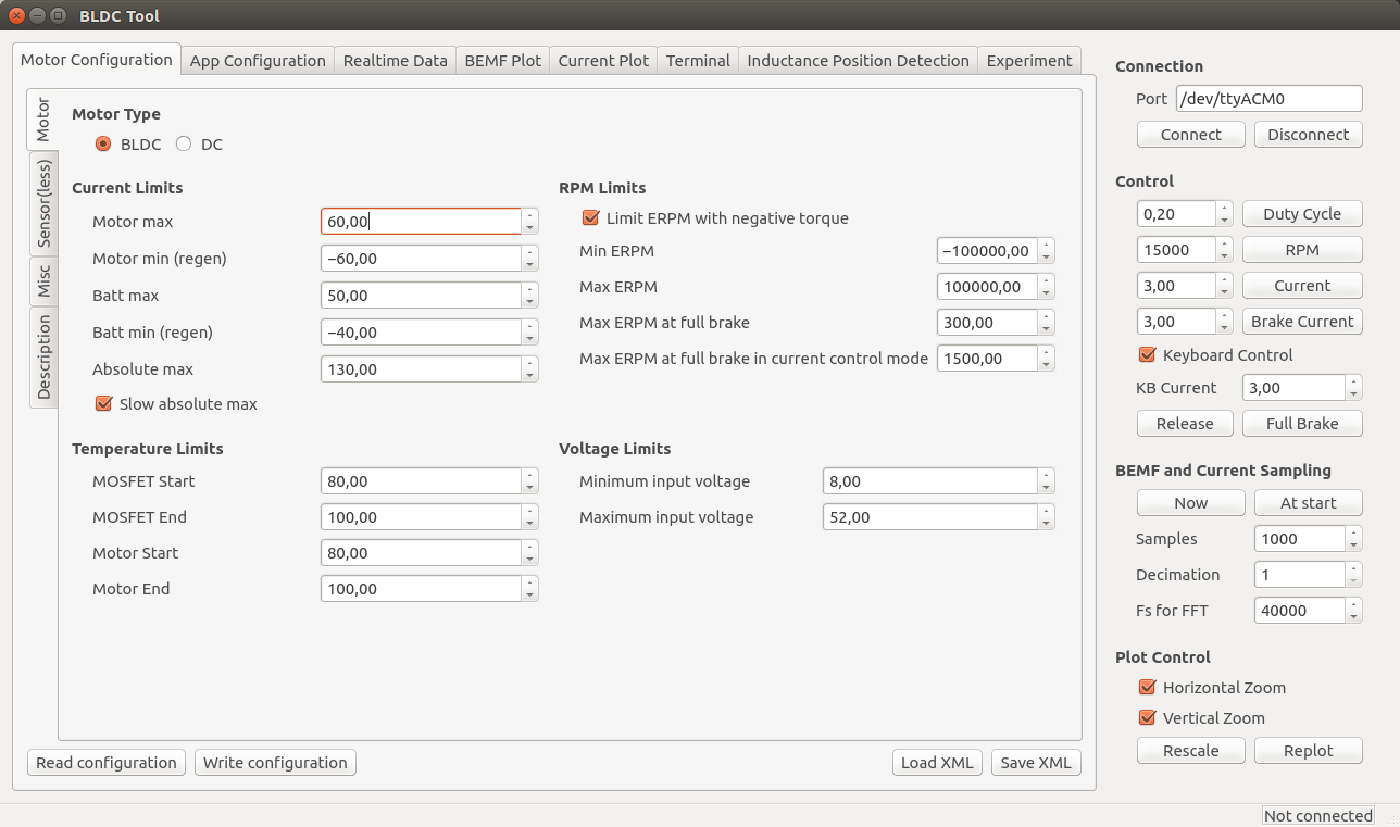
Note: These limits are not foolproof. If you set them too high, you can damage the ESC and/or the motor.
- Current
- Separate limits for acceleration and braking current.
- Separate limits for motor and battery currents.
- “Absolute max” is checked in every PWM switching cycle and used in case the soft back-off strategy for the other limits doesn’t work. I usually set it way higher than the other limits because soft back-off is preferred rather than switching off the motor with a fault code, but it should never be higher than 150A.
- The “Slow absolute max” box will make sure that a filtered version of the maximum current limit is used. This is useful if there is much noise and that fault code kicks in all the time. I usually have it ticked.
- Temperature
- At the “Start” temperature, the current will become more and more limited linearly until the “End” temperature, where the output is switched off completely. Setting them about 20 degrees apart will make the ESC slowly decrease the maximum output current as it gets too warm instead of abruptly switching everything off.
- MOSFET temps (on the ESC) are implemented and working, but motor temps are not implemented yet. They will require an external temperature sensor in the motor. The software implementation is rather simple since I can just copy most of the MOSFET temperature limit code.
- RPM
- Max and Min ERPM are hard RPM limits. It is preferable to use the soft application RPM limits instead if possible.
- “Max ERPM at full brake” (should change the name…) is the highest opposing RPM at which a direction change is allowed. Setting this too high will cause cogging when moving in one direction and giving high throttle in the other direction. On my longboard I have it at 300 and my RC car has it a bit higher.
- “Max ERPM at full brake in CC mode” is the highest RPM at which applying full brake by shorting all the motor windings is allowed. Setting this value too high can cause much mechanical stress in some circumstances. I have it at 1500 for all my applications.
- Voltage
- The minimum and maximum input voltage.
- NOTE: I changed the voltage dividers in hardware 2015-01-22. If you have built the PCB before that, the maximum voltage can’t be more than 52V. The difference is whether the PCB has 33k or 39k resistors. 33k means that maximum 52V can be measured. The latest PCBs (with 39k resistors) can measure 60V, but you should have some margin on your supply voltage to be safe. You can of course replace all 33k resistors with 39k and measure up to 60V.
Once the ESC is configured for your motor, you can use the up and down arrow keys to run the motor forwards or reverse in current control mote, or the right and left arrow keys to run the motor forwards and reverse in duty cycle mode. The buttons in the right-hand side of the GUI can also be used.
Misc
Here are the rest of the motor configuration parameters. You probably want to experiment with Startup boost if you are using current control. The rest of the parameters can be left as their default values unless you have some specific reason to change them.
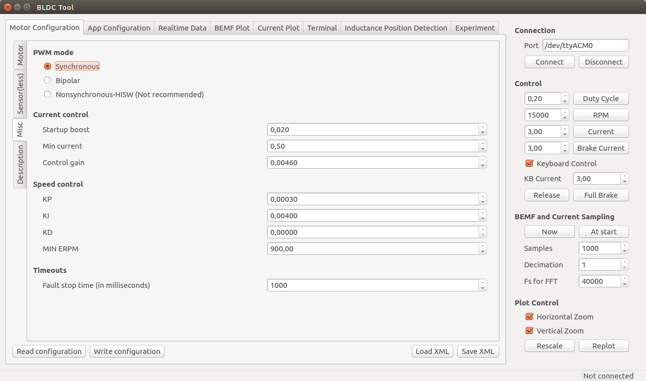
- PWM mode
- Synchronous is recommended and the best choice for a majority of all motors. If you have some weird motor, Bipolar could work better, but it probably won’t. Nonsynchronous is only for experimentation and can kill the ESC if you are unlucky.
- Current control
- Startup boost is the minimum duty cycle to use when using current control. If the motor is to weak when you are just starting, you can increase this parameter a bit until it feels right. The range is 0.0 to 1.0, where 1.0 is full throttle (which you shouldn’t use.). A sane range is up to 0.15 or so.
- Min current is the minimum allowed current. There should be no reason to change this, so leave it at the default value.
- Control gain is the gain used by the current controller. Increasing it makes the current response faster, but also increases the risk of getting an unstable system where the ESC can get damaged. Only change this if you know what you are doing.
- Speed control
- The PID parameters for the speed controller. Only change them if you know what you are doing.
- Timeouts
- Fault stop time is the amount of milliseconds that the ESC should be completely switched of when a fault code arises. After that time, it will switch on and try to listen for commands again.
Application Configuration
First, click “Read configuration” to get the current configuration from the ESC. After that, select which application to use and configure that application.

- Controller ID is the ID of this VESC. If multiple VESCs are connected over CAN-bus, they must have different IDs.
- Send status over CAN has to be enabled to make other VESCs aware of this VESC and some of its current state. It should be enabled for all slave VESCs when connecting multiple VESCs over CAN-bus.
- Changing application requires a reboot. There is a button for that. After a reboot, you have to click connect again.
- Timeout is the amount of milliseconds after which the motor should be shut off in case the control signal is missing.
- “Brake current to use…” can be set to make the motor brake with a certain current when a timeout occurs instead of just releasing it.
PPM
The signal that a normal RC receiver outputs is a PPM signal, so this can be used when connecting an RC receiver to the servo port.
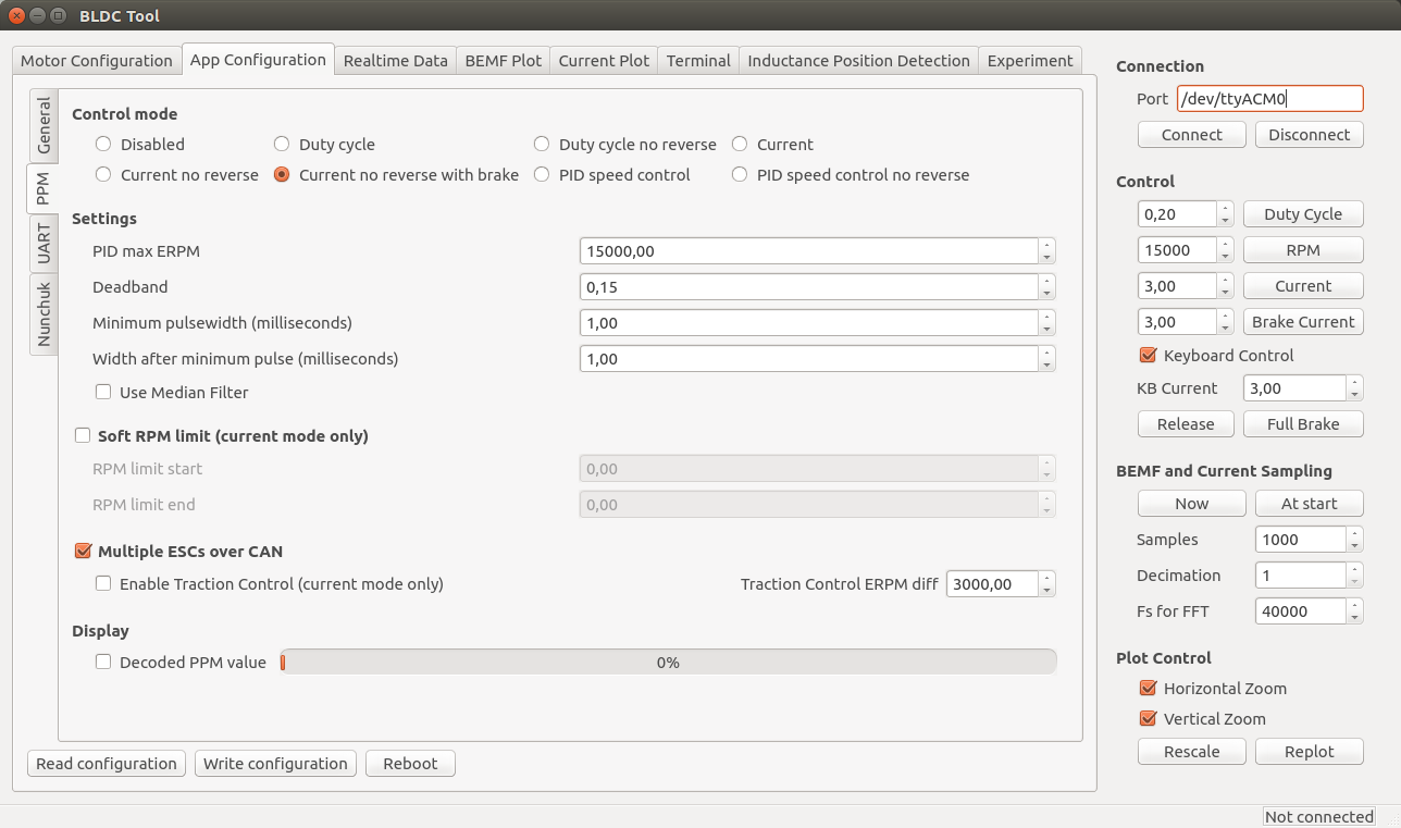
- Control mode
- Disabled: Nothing at all, motor is off.
- Current: Torque control. This is what I prefer since it feels most natural. I haven’t seen hobby ESCs that have current control.
- Current no reverse: Save as above, but no reverse function. Note that centring the now will give half throttle.
- Current no reverse with brake: No reverse, but centre is zero torque. Reversing will brake, but not change motor direction.
- Duty cycle: Duty cycle or voltage control. What most hobby ESCs use.
- PID speed control: The throttle command is intepreted as a speed set command and closed-loop control is used to maintain that speed. “PID max ERPM” sets what max throttle should be interpreted as.
- Settings
- Deadband: how much span in the centre of the throttle should be ignored.
- Minimum and maximum pulsewidth: The timing interpretation of the PPM signal can be adjusted in case your receiver doesn’t follow the specification or it you have some other reason to change it. Setting “Control mode” to “Disabled” and ticking display decoded PPM value is useful when adjusting these.
- Use Median Filter enables a filter that is very useful when there are glitches on the PPM signal. If you have a quadcopter application, you should disable the filter and make sure that there are no glitches since a filter introduces some delay.
- Soft RPM limit.
- Speed limit that can be used in current control mode. Setting the start and end limits a bit apart will result in a soft torque decay when approaching the speed limit.
- Multiple ESCs over CAN can be enabled to connect several VESCs over CAN bus. All VESCs must have different Controller ID and the slave VESCs must have Send status over CAN enabled (see the general tab under app configuration). The slave VESCs don’t need to have any application enabled since they will just be listening for CAN commands. Traction control can also be enabled, which reduces the torque on motors that spin faster than the slowest motor proportional to their speed difference. To connect VESCs over CAN-bus, connect the CANH and CANL signals between them. DO NOT connect 5v and GND because that is likely to cause ground loops which can reset and/or kill the VESCs.
Nunchuk
The Nyko Kama wireless nunchuk can also be used to control the ESC. Note that not all nunchuks for the nintendo wii will work, because they slightly differently.
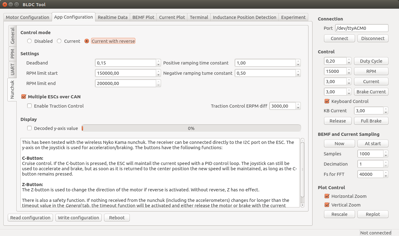
- Control mode
- Disabled or current control with or without reverse. If reverse is used, the Z button is used to toggle a direction change.
- Settings
- Deadband: The span in the centre of the throttle that should be ignored.
- RPM limits: Limit the electrical RPM of the motor. The start value is the point where the torque should start decreasing and the end value is the point where the output will be switched off. Setting them slightly apart will give a soft RPM limit. Setting them very high will disable the RPM limit.
- Ramping time constants: How fast the throttle command should be followed, in seconds.
- Multiple ESCs over CAN can be enabled to connect several VESCs over CAN bus. All VESCs must have different Controller ID and the slave VESCs must have Send status over CAN enabled (see the general tab under app configuration). The slave VESCs don’t need to have any application enabled since they will just be listening for CAN commands. Traction control can also be enabled, which reduces the torque on motors that spin faster than the slowest motor proportional to their speed difference. To connect VESCs over CAN-bus, connect the CANH and CANL signals between them. DO NOT connect 5v and GND because that is likely to cause ground loops which can reset and/or kill the VESCs.
A video where I test this:
Realtime Data Display
Use the “Realtime Data” tab to display realtime information from the ESC. Make sure that the “Activate sampling” box is checked.
Common Problems and Solutions
As I encounter different problems, I will put them here together with possible solutions for reference.
Uploading the firmware does not work.
- Make sure that you have followed all steps in the tutorial, including adding udev rules to access the programmer without being root.
- Don’t use a too long cable for the SWD connector.
- Make sure that you have a working programmer. I got one from ebay that didn’t work at all and one that died quickly. Otherwise they have been reliable though.
A DRV8302 fault code appears as soon as the motor starts.
- Make sure that R16 is not mounted (see the comment in the schematic).
Connecting to VESC via BLDC Tool does not work.
- Run dmesg to see which ttyACMx port gets assigned to VESC when plugging in the mini-usb cable.
- Make sure that the mini-usb cable is plugged in and that power is connected to VESC. Connecting BLDC Tool is not done via the SWD programmer, but via the mini-usb port.
- If you are using a different usb-connector than the one from the BOM, make sure that the order of the pins is correct. The connector in the BOM is upside-down, so a connector that isn’t will have all the pins mirrored.
My motor is not running properly.
- Make sure that you have configured VESC for your motor as described above. VESC is not plug-and-play and needs an individual configuration for each motor. Without the configuration, the motor will run poorly or not at all. Read the instructions carefully.
Is there a way to “boost” the startup of my motor when using current control?
- Yes, the Startup boost option under Motor Configuration > Misc tab in BLDC Tool can be adjusted as described above.
Update: I have ordered assembled VESCs, some of them are for sale
Update about this update: There are no assembled ESCs left. However, If you are interested in assembled VESCs you can still send me an email as described below so that I can put you on my extra list. If someone changes their mind or if there are other problems, I can send you VESCs that get left.
I have ordered 100 assembled VESCs and they will arrive this or next week. I don’t need all of them, so I will sell some of them for 115€ + shipping. Worldwide shipping with tracking is 20€ per order (which can contain more than one VESC). Shipping within Sweden is less expensive and I will update this post as soon as I know the price. You can contact me by email if you are interested (benjamin at vedder.se). Tell me how many VESCs you’d like and your address, and I will reply with an email that confirms that I have put you in my list. Later, when I have figured out how to accept payments, I will send another email with information about how to do that. As soon as I receive your payment, I will ship the VESC(s) to you and send an email with tracking information
I will update this information in the coming days, so make sure to check if there are updates.

A small note on this page: Your version of gcc-arm-none-eabi is not found. A newer version can be found: sudo apt-get install gcc-arm-none-eabi=4.9.3.2015q1-0trusty13
The current version is now 4.9.3.2015q2-1trusty1.
Some requests for the new PCB version of the VESC that Benjamin is working on:
* All MOSFET’s on one side for easier cooling and mounting (He is already working on this, and I’ll be releasing a open-source enclosure for this)
* Breakout a 3.3V port for powering external sensors or a simple Arduino board or to be able to add lets say BLE (Bluetooth low energy notifications to your phone of battery, amps or other stats)
* Easy ability to add two or more VESC together for dual or quad drive systems with control from just one i2c/Wii Controller
Documentation (Willing to help here, but I don’t know the CAN-bus design)
* Document the CAN-bus communication used by the VESC to more easily build additional features surrounding it. (Like how to get current voltage and amps , on/off, or to trigger certain settings)
* Documenting wiring and the code/execution structure for additional applications on the STM32F4 microcontroller
Hi, very nice project. For the CAN Bus I would like to propose to give the opportunity to use the CANaerospace protocol: http://www.canaerospace.com
Some nice-to-have features:
– Isolated CAN tranceiver
– Power Input not in the middle of the PCB
– 5V/12V FAN output
If someone would be interested, I would contribute/donate for the new PCBs with above mentioned new features
Hi, very nice project!
A question after watching the movies, what is the difference between motor current and battery current?
Doesn’t all current go through the motor?
And how do you measure the battery current? You only seem to have shunts for the motor phases.
Thanks! 🙂
@Ekman – Can’t wait for those new updates on VESC 🙂
Hi,Benjamin.Excellent project!
When i debug the project(press “run”),I get the following information:
/home/forrest/workspace/insist/build/BLDC_4_ChibiOS.elf: 1: /home/forrest/workspace/insist/build/BLDC_4_ChibiOS.elf: Syntax error: word unexpected (expecting “)”)
Thank you so much
forrest
would you please tell me why this happens? Did you have the similar experiences when you debug your project?
Hi, perfect project.
I like use this ECS for big multicopter. Can i buy ready PCB?
Hey,
really nice project. I allready started to read the source code, it is a lot 😉
i have some basic questions, which i couldnt answer yet.
Are you using highside or lowside pwm?
are you sampling the phase voltages only once per pwm cycle (during high or low pwm)?
and how do you compensate the phase error through the FIR filters?
there are only a few comments, so it is sometimes hard to understand the code.
really nice work!!!
Thank you,
Nils
Hi,
Thanks 🙂
You can choose which PWM strategy to use in the misc tab of bldc tool, but the synchronous one which I strongly recommend has the low side on on one phase and alters between the high and low side on the other phase. This is sometimes called active freewheeling or synchronous rectification.
The FIR filters are only used on the absolute or “emergency” overcurrent protection, the duty cycle tracking and the kv estimator (which only is a terminal command), so the critical parts of the current control loop and the commutation algorithm don’t use the filtered values in order to minimize delay. For the other filters, I tried to make them as short as possible to minimize the delay and computation requirements, so there are no delay issues with the duty cycle tracking either.
/Benjamin
Hey,
what is the advantage of highside pwm?
so are you measuring the backemf while all phases are low?
can you maybe let me know, where i can find the backemf filter? i am really interested in this part of the code.
Thanks for your respond,
Nils
Synchronous PWM is not high-side PWM, both the high side and the low side are switching the same amount on the phase that is switching.
No, the back-emf is measured during the on-time. The currents are measured while all phases are low though.
There is no filter for position tracking based on back-emf, only for analysing how much duty cycle the motor speed corresponds to. This is where the samples are added to the filter:
https://github.com/vedderb/bldc/blob/master/mcpwm.c#L1688
and this is where it is updated when the motor is not driven:
https://github.com/vedderb/bldc/blob/master/mcpwm.c#L1341
this is where the duty cycle is estimated based on the input voltage and the direction the motor is rotating in when the motor is not driven:
https://github.com/vedderb/bldc/blob/master/mcpwm.c#L1403
The reason to estimate the duty cycle is to start at the correct operating point when the motor is already spinning. Otherwise there would be very high currents when starting to drive the motor at a duty cycle far away from the back-emf.
hey,
maybe i mixed the name of it up. but when you power two phases, you could either put the switch on phase A on high and do pwm on phase B or do pwm on phase A and but phase B constant low.
thank you,
Nils
In the BOM there are 6 4n7 capacitors, but on the hardware design there are only 4 used. Where are the other 2 going?
“81-GRM39X472J50D CAP 4.7n, 50V, 0603 6 C4-C7”
There should only be 4. A while ago I had another filter, but I removed that. I will update the BOM.
Hi
Which firmware version has Synchronous rectification ?
It’s important for me since my application have high load below max duty cycle.
I use current control.
This is so impressive, I love that there are people like you in the world! You could add support for DC motors without changing the hardware. You’d just use 2 of the phases. DC motor software is nothing compared to Brushless drives!
Looking forward to hearing about those assembled boards you’ve ordered.
Thanks! There already is support for DC motors 🙂
Pingback: VESC - 3-12S Open source ESC - R/C Tech Forums
We soldered some VESCs, and one doesn’t work: the firmware can be programmed onto the ARM chip, but when attaching the LIPO battery, the board gets hot soon.
Does anyone have some trouble-shooting ideas?
I have the same problem. What was the solution in your case?
@Jeff Some of the boards that got hot were fixed by replacing the CANBUS tranceiver, apparently when using two VESCs each with separate battery, that transceiver can get damaged. Various other VESC boards had a problem with the ground of the DRV8032, so replacing that helped too.
This is a very cool project! I tried the ESC32 that used STM32F103 for the CPU, but the performance of that ESC is not good. I will try this soon, but I wonder, is it necessary to use STM32F4 CPU?
hi Benjamin
Thank you for your sharing Project.
Recently, i am following project with other Motor(ipower GBM4008H-150T).
uploading firmware, PC connection and disabled all other interface are Ok..
In addition, i finished detection running. i think it spin up well also.
but i got detection failed message.
what i miss?..can you advice me?
Very interesting project!
Have you already managed to implement an own flux-observer like in the instaSpinFoc or do you use an SMO? Had a short look at your source code but could not find the angle estimation. Perhaps i should search better 😉
I haven’t implemented FOC yet, but I’m working on it. I will most likely use a SMO and possibly combine it with HFI for very low speeds.
I also use an SMO, with filters like in AN1078. It works pretty well, but I’m not able to run under 1Hz like the instaspin.
But how do you run your longboard and the RC car in your “Testing my custom ESC on a 1:8 buggy ” video in the sensorless mode?
The motors I have cannot run under 1hz because they have too high cogging torque. In the longboard video the motor runs at about 1Hz when it runs the slowest, but that is with bldc commutation. I’m working on FOC now and will hopefully have some results soon.
Okay, thank you for the answer 🙂
I have two more questions:
I want to design my own ESC.
1. Is it right that you use the D5 TVS 5V
to set the output voltage of the buck converter from DRV8302?
2. Do I need the CAN bus transceiver if the communikation partners will also use just 3v3?
Hi, I would like to use my own controller with VESC. What interface is best to use (I want to send motor rpm, battery charge level etc to controller) ? May I somehow connect nRF24 to VESC, or is it better to use separate microcontroller for radio transmission, and send commands and read data from VESC using I2C, or UART ? Is it possible to read rpm and battery charge level with I2C or UART ?
I have implemented the interface and some functionality for the nrf24l01, but it is not complete yet. Implementing the rest is easy and you can get motor rpm, current, battery voltage, wh used etc. You can also use UART or CAN-bus if you’d like.
Great Project.
thanks for all.
i have tried to open the Hardware Data in Kicad. i got an Failture on open the PCB:
Fehler beim Einlesen der Platine.
PARSE_ERROR: Expecting ‘number’ in input/source “/home/markus/BLDC/bldc-hardware/design/BLDC_4.kicad_pcb”, line 84, offset 23
from /build/buildd/kicad-0.20131208+bzr4024/common/dsnlexer.cpp : Expecting() : line 285
have you an idear for this failture?
Thanks for Help
Hi Markus,
Do you have kicad from the repositories or did you build it yourself? I think the version in the repositories is quite old. The install script is quite easy to use, so I recommend doing that.
Hey Benjamin, we’ve just discovered your OSHW ESC over at RCGroups and I was considering replacing the STM with a AVR (something like a 328P or a 32U4 or even a older 8A) so that we could run either SimonK or BLHeli FW on it. I was wondering your opinion on that. I would be willing to donate if that would sway your opinion.
Also, tho I have KiCAD installed I prefer to work in Eagle, have you ever found a ULP to import KiCAD to eagle (there are multiple ULP’s for going the other way)
Hi,
The AVRs are way too slow to run the algorithms I’m using now or to have any decent current limiting, so I’m not interested in that. Running FOC on AVRs will also be impossible. Also, I see no reason for me to invest time in making the design in eagle because 1) eagle is not as good as kicad in my opinion, and 2) eagle is not open source (which is very important for me).
I’ve been looking for a preferably open source BLDC motor controller for a little while now and there seem to be a lot of these projects. However, most if not all but yours seems to have stalled or gone cold long ago. I will be devouring as much as I can about your controller over the next few days and will be hopefully starting work on one at the first of next month. As much as I’ve read already I was sad to see I missed my shot at purchasing a completed version, but will do what I need to do. It’s been nearly 25 years since I earned my degree in electrical engineering, I’m wishing now I had actually gone into that field and wasn’t looking at a serious refresher course as well as catching up on a quarter of a decade of advances. The last time I soldered anything the components were gargantuan compared to today’s parts. Anyway, I want to say thank you for such a thorough and lively project. It is going to make my current foray into building an electric trike much more enjoyable. Cheers!
Thanks 🙂
If you send me an email with your address, I can put you on my extra list. There might be some VESCs left if someone changes their mind.
Hi Benjamin,
could you please give an update about the VESC pre-orders? Have they arrived yet?
best regards,
Nicolas
Hi Nicolas,
The PCBs arrived two days ago and work fine. The SWD connector is not mounted because there was a problem with the assembly, so I have to handsolder all of them. I will send emails about the payment today or tomorrow if I have time to figure out how to do the shipping. Before I ship the VESCs, I would like to work a bit more on the bootloader so that bldc tool can be used to update the firmware (it does work now, but I would like to test it a bit more). Finally, I would like to make a video tutorial about how to solder wires to the VESC and how to do the configuration.
/Benjamin
Pingback: Maker Faire 2015 | Santa Barbara Hackerspace
Hi Benjamin,
Great project!
I also purchased some VESC v4.7 from Hackvana and was trying desperately to solder the board. After 4 attempts, I still cant power it up. It seems like I have no 5V buck output from the DRV8302 but I dont know why. the DRV8302 was properly soldered using hot air gun and solder paste for the PowerPad. I check the diodes for any avalanche breakdown but none. I also tried to remove the voltage regulator and power the board without it but still no hope for the 5V output (plus fried some components). Without the 5V, the MCU cant operate, blue LED doesnt light up. However, I noticed the voltage across the lower half mosfets is zero. I also neglect the Hall sensor circuit to save time for the last couple of boards. Can you please help me identify the problems? Did I miss something? Thank you very much.
Martin
Hi Martin,
Can you measure the resistance on the 5V and the 3.3V nets?
Hi Benjamin,
Thanks for your reply. I just found out the problem. I soldered the board and immediately wash off the flux when its still hot with Flux Remover liquid so it cooled down the board so fast that some components were damaged. I just succeeded with the last board. I still have problem in loading the firmware with openOCD. I guess i miss some dependencies.
Hi Benjamin,
I just finished loading the firmware and run the BLDC-Tool. However, as soon as I started the detection, the common fault code drv8302 appreared. I did some goolge and found that you asked the same question 2 years ago on TI forum (https://e2e.ti.com/support/applications/motor_drivers/f/38/t/227363) and you pointed that the voltage spike caused the fault.
So, what could possibly be my case?
Are one or some mosfets dead?
FYI, the DRV8302 is correctly soldered as the buck converter is working.
Thank you very much
Martin
Hi Martin,
When posted that question I had some hardware issues, and since that I have redesigned the PCB completely. Did you use my design, or did you make your own? If you used my design, did you mount R16?
Hi Ben,
Thanks for your reply. I purchased your v4.7 board from Hackvana. I didnt mount R16 or C26 or R6. However, I salvaged some capacitors from a failed board (failed due to short or something) to this newly-built board. This time I have everything work except for the DRV8302 fault code: the blue LED light up, red LED also light up (I exchange the red for the green), the green (or red) blinks 3 times whenever fault is detected. I’m also able to connect the board to GUI tool and read the real-time data. Just like a guy (“benj”) on Endless-sphere also experience the same fault with Onloop beta board: http://endless-sphere.com/forums/viewtopic.php?f=35&t=63540&start=650
Do you think I need to replace some capacitors? I bought these from your BOM list. For the resistors, I bought them with the same specs, same price but color “black”.
Best Regards
Martin
Hi Benjamin,
on witch IDE do you Debug your Software Project?
can you upload an Project File for this IDE so it could be easier to run.
thanks for help
Hi Benjamin!
Thank you for this amazing project!
I would like to use your controller as a servo drive controller. As far as I can tell, it is not possible to use it in this way at the current development level because it needs sensor driven FOD control, is that correct?
Important to me is a strong hold function that is fairly efficient as well as 100% startup torque and, in case the controller loses “grip”, the ability of the controller to move the rotor back to the original position when it’s already moving/rotating in the wrong direction (there is a sensor for this, so the controller would get input regarding how far it has to move).
Does the PID speed control mode have a few of these capabilities?
Thank you and best regards,
Matt
Matt, thanks!
Hi Matt,
I have done this with a DC motor and a rotary encoder:
https://www.youtube.com/watch?v=qqNOx57f2OU
It should also work with a brushless motor, but I don’t have one to test with right now. Position control and FOC have high priority now, so I will work more on that soon.
I first want to say great project. I have taken time to solder up some boards with a few questions. What does the blue led stand for when it is on?
The blue led just indicates that power is connected.
http://www.ebay.com.au/itm/VESC-Vedder-ESC-v4-7-PCB-Customisable-Electronic-Speed-Controller-/151688949511?_trkparms=aid=111001&algo=REC.SEED&ao=1&asc=20131017132637&meid=123387438e434bbab7846341c1d64ad0&pid=100033&rk=1&rkt=1&sd=151688949511&_trksid=p2045573.c100033.m2042&quantity=1&autorefresh=true
And this guy wants to make money from your work
Hey, yep that’s my listing.
I’m not really making any money, eBay’s 10% commission, & free UK posting… And anyway, I’ve made a donation to this project. But I can remove the listing straight away if you want?
I see no problem with it at all, I think it is nice that you made the listing. If you buy 10 pieces from hackvana and just need a few it is great that other can make use of your spare PCBs.
Maybe it is a good idea to add a pulldown resistor to servo pwm input. It is dangarous when the pin is floating.
Yes, that could prevent some problems in case the input is active and floating. I will start by adding a pulldown in software (the stm32f4 pins support that).
Hi Benjamin,
do you have any problems powering the TC2117 or the DRV8302s internal Buck Converter in reverse?
For example when you just connect the SWD or the USB without the battery.
Or the battery and the SWD or/and USB at the same time.
Just asking because there aren’t any diodes or coupling resistors.
Powering the TC2117 in reverse is no problem. The USB actually doesn’t have the 5V connected at all, so in order to use it you have to connect a battery at the same time.
Hello,
Great project!
I would like to use these ESC in an self balancing two wheel scooter. I plan to use 500W-1000W hub Motors with hall effect sensors.
Is a torque control mode integrated in the software yet, so that it is possible to increase/decrease torque regardless to the turning direction?
Is the CAN-Bus fully implemented and the interface documented (I know that I have to solder a transceiver on an extra board)?
Could I use the IRFS7530 MOSFETs which have a lower RDSon (1,4mOhm max. vs. 2.1mOhm) but a higher Gate Charge (max. 354nC vs. 300nC)?
Do you recommend 36V or 48V for the controller/motor combination?
Thank you,
Tobias
Sorry I answered to your old post first, my comment there could be deleted.
Torque control is implemented and working. CAN-bus also is, but documentation is lacking. The latest PCBs have a CAN-transceiver, so you don’t have to put it on an extra board. The latest BOM has the irfs7530 mosfets already and they are working fine 🙂 Both 36V and 48V should work fine for these motors.
Thanks for the answer.
For the CAN-bus documentation I read the .c and .h files 😉
Is it possible to use two ESCs in slave mode and send them different torque requests?
Master would be a Teensy3.1 which runs the control loop and commands the VESCs.
Do you suggest sensorless mode or sensored mode (three hall sensors) for my application?
48V seems a bit to much for 60V MOSFETs (for me) because of the inductance of the motor and voltage spikes at shut off from the MOSFETs so I try it with 36V first.
Thanks,
Tobias
Hello Benjamin,
I’m a member over at endless-sphere and found your VESC on the forum.
I made a friction drive system based on the information gathered from the same forum for my mountain bike. I documented my work and submitted to a site called instructables. Please see link: http://www.instructables.com/id/Friction-drive-build-for-bikes/
I’m now looking for a better, more comprehensive esc system that will allow me to get more out of my 2 lipo 5000 mAh 20-30c 5s 18.5v batteries.
I want to be able to change the power settings and whatever else needed to get a little more life from my batteries, using like an economy setup, I hope this makes sense and the VESC would be suited.
Best regards
Blan
Tried to contact you by mail to get some of your controllers… but no reply yet…
So i’m trying here.
How much for 4 controllers ?
Sorry about that. I get quite a lot of emails and I miss replying sometimes. I was also away all of last week and didn’t have time to go through all my emails.
Unfortunately I don’t have any VESCs left from the batch, but there will be another batch later this year.
Hi.
Great project.
You have profound knowlege!
I would like to purchase a board. Do you have any left over?
Thanks, Matthias
Hi,
Thanks for well done board. But now comes my problem: I’m not realy used with linux. I get problems during the install with:
sudo apt-get install gcc-arm-none-eabi=4.9.3.2015q1-0trusty13
That the Version for gcc-arm-none-eabi was not found. Can anyone help?
Thanks
Andy
I’m using ubuntu 15.04 in VirtualBox VM.
Hi Andy,
That repository does not work with Ubuntu 15.04. You can still get it working in 15.04, but if possible I recommend that you install Ubuntu 14.04 since 14.04 is a LTS release.
Thanks,
Then I will try to get an 14.04 appliance. Keep you informe here.
Hi, Benjamin,
Nice project 😉 I just soldered one of your older boards and I have a problem. I connected HDD motor and detection fails every possible way I try. It also spits “Writing ser_info struct failed” in terminal. No faults reported from bldc-tool. Spinning motor by hand gives plausible readings in real-time tab but rotor position sensoring fails as it is jumping around like crazy. What can be the issue? DRV is soldered correctly as voltages are OK. R16 and other stuff you mentioned in updates are not soldered. What can be the issue? 🙂
I just tested it with servo input. BLDC-tool reports speed ranging 0-100%-0 in ~4sec range. Motor standing still. Real-time data shows duty cycle increasing/decreasing. Current spikes to 0.4A only on falling edge of duty cycle (when it is decreasing from 100%). Why could it be? :/
Is there any fault code?
HDD motors don’t work too well with auto detection. I think there is one configuration that works for hdd motors, but most likely you have to do some manual tuning.
The ser_info_struct error always shows up with the emulated serial port, so that is no problem.
Hi,
thanks for answers. No there is no fault code. I had one shorted MOSFET, but now everything is ok and I still can’t get that bloody HDD motor started. Can you provide more info on that one config for HDD motors? I am waiting for a bigger motor and am willing to play with smaller one until that.
You should really try a different motor if possible. HDD motors are by far the trickiest ones to get running with VESC since they differ from other motors so much and I haven’t put any effort in making the auto detection work for them. You could give this config a try, but I don’t know if it will work for your hdd motor:
https://github.com/vedderb/bldc-tool/blob/master/mc_configurations/hdd.xml
Thanks, I tried it with no luck. Still waiting for another motor. Should it stand still? It hasn’t moved a bit. Is it really that different that it doesn’t even try to move? Live feed of data shows current, duty coming up and down, but motor stands perfectly still. Maybe there is something wrong with my circuit?
Hi Benjamin
I got my VESC 2 weeks ago and I am still very impressed of its sensorless performance.
Nevertheless my application demands high torque, low speed dead starts and sometimes I experience cogging.
I saw your video on position control with encoders and thought about adding a quadrature encoder to my motor to enable active breaking and low speed, high torque startup.
My questions:
1) I saw in your github repository that there are versions of the firmware that support encoders. How much of the code is already implemented to use encoders for motor control?
2)I am willing to invest time to code the stuff I need by myself. I am not an expert in programming, but I’m quite used to basic and some advanced applications, although I never worked with ChibiOS. How would you estimate the effort for me to get into your code and work on it?
Thanks and best regards,
Lukas
I used the encoder for a brushed motor, so it is not implemented for brushless motors yet. I will do that once I have a brushless motor with an encoder. You can use hall sensors though. The hall sensor implementation should be working well.
It should be quite easy to write custom applications, but the motor control code is quite cryptic. I will write a tutorial about how to make applications soon.
Hi Ben,
I heard that there have been problems with high KV motors running on 12S.
I have built a setup with 230KV motors with 10S (gearing 36/15). Do you think it would be OK to use with your VESC ??
A 230kv 14 pole motor on 10s should work fine.
Almost the same question : I have 213kv motor and 12S battery. Will it be safe to run with this setup if I set MAX_ERPM limit to ~70000?
A 213kv 14-pole motor should work on 12s.
almost the same question: I have 230kv motor and 12S battery. Will it be safe to run?
Hey Benjamin,
i have a question regarding measuring of the back emf.
when the motor is spinning (without current), how do you measure all phase voltages simultaneously? do you have one phase voltage connected to ground to get a reference?
Cheers,
Alex
I compute the virtual ground by simple taking the average of all phase voltages.
Hey,
what i meant is, how do you measure the voltage, when all phases are floating?
Cheers,
Nils
The phase voltages will be somewhere between 0V and VBATT, even when they are floating. By sampling all voltages at the same time, taking the average of that and substracting that from every phase voltage, I can get the individual phase voltages referenced to the virtual ground.
Hello,
great work, thanks so much..
Iam one of the few using a twist throttle – ebike application with your VESC..
constructed by silviasol, he added the 3-wires to the correct plug..
So .. I was wondering what is the correct setup for a 3-wire twist throttle ???
I did get it to work only all apps are disabled..
I followed the PPM setup method to get
integrator limit and BEMF coupling parameters..
however can I make any adjustments ??
My throttle is just ten bucks model.. But only about the first half of the twist is needed to hit max battery limit.. Can it be set for a wider range twist action ??
I think in one config. I had ADC enabled.. but when twisting the throttle the motor would jiggle back and forth slightly… so I have not ventured any further…thnkyou for any help
If you run in current mode, the motor will go to full speed with just a little throttle. You have to put load on the motor to notice the difference. What is the graph in BLDC tool showing?
Hey,
I’m running a Debian-Jessie so the repository for compiling the firmware “ppa:terry.guo/gcc-arm-embedded” does not install. Do you think I can use the
“binutils-arm-none-eabi” and “gcc-arm-none-eabi” toolchain from Debian to get the firmware compiled or do I have to switch to ubuntu?
Thanks for any hints
Dude
I don’t think the arm toolchain that comes with debian works well. You can also just use the linux archive from here:
https://launchpad.net/gcc-arm-embedded
and use the full path for the compiler where you unpack it.
Hello,
I work on Jessie too and used the debian build in Toolchain. It compiles the code very well and flashing the ESC works.
The GUI could connect to the ESCs also. But I haven´t tested with a motor yet but I think that shouldn´t be a problem because the debian build in toolchain “gcc-arm-none-eabi” ist for embedded Cortex M* processors.
Regards,
Tobias
Hi Benjamin,
super project, nice explanations. Thanks super good work.
I try to understand the schematics and most of the time it makes sense but why is R36 connected to H1_low and not to H2_low. I do not understand this, can you help ?
Regards
Andre
Hi Andre,
Thanks!
I only connected it like this because it made routing easier. There is only a shunt in between, so the potential is virtually the same in H1_low and H2_low.
I’m not sure, but it seems that the guys from Inbord (Monolith or M1 E-Bord) use the customized version of your project ….
http://static1.squarespace.com/static/550b3040e4b0498b4aaddfa9/t/556f5ec2e4b04c98f309f28f/1433362150299/pcb.png?format=750w
from http://www.inboardskate.com/blog/
and https://www.facebook.com/inboardskate/photos/pb.1547191082218310.-2207520000.1435929566./1617553908515360/?type=1&theater
Your thoughts?
Hi Benjamin,
I’ve read the source code to find out how to control the VESCs via CAN-Bus. I would like to share my gained experiences and would like to ask you if I’m right with my assumptions.
The CAN packet should have the following properties:
– DLC should be 4 (4 byte of Data should be transferred)
the value given to the matching functions (look below) is calculated in the following way
value = byte[0] << 24 || byte[1] << 16 || byte[2] << 8 || byte[4]
– extended identifier has to be activated (ID range from 0x00000000 to 0x3FFFFFFF)
– the first two bytes of the ID (the right ones) should be "1" (ID=255) or the Controller ID (configured in the VESC GUI) then the VESC will process the received CAN-Frame
– you have to choose the third byte from the ID according to the mode you would like to use with your VESC. The third byte should look like the following list.
0x000000ID – CAN_PACKET_SET_DUTY
The 4 data bytes should contain the desired duty cycle multiplied by 100000.0 (the comm_can.c devide the received value by this gain)
0x000001ID – CAN_PACKET_SET_CURRENT
The 4 data bytes should contain the desired current multiplied by 1000.0 (the comm_can.c devide the received value by this gain)
0x000002ID – CAN_PACKET_SET_CURRENT_BRAKE
The 4 data bytes should contain the desired brake current multiplied by 1000.0 (the comm_can.c devide the received value by this gain)
0x000003ID – CAN_PACKET_SET_RPM
The 4 data bytes should contain the desired rpm without mutliplication
0x000004ID – CAN_PACKET_SET_POS
The 4 data bytes should contain the desired position multiplied by 1000000.0 (the comm_can.c devide the received value by this gain)
0x000005ID – CAN_PACKET_FILL_RX_BUFFER
I don't know what the FILL_RX_BUFFER function should do
0x000006ID – CAN_PACKET_FILL_RX_BUFFER_LONG
I don't know what the FILL_RX_BUFFER_LONG function should do
0x000007ID – CAN_PACKET_PROCESS_RX_BUFFER
I don't know what the FILL_RX_BUFFER function should do
0x000008ID – CAN_PACKET_PROCESS_SHORT_BUFFER
I don't know what the FILL_RX_BUFFER function should do
0x000009** – CAN_PACKET_STATUS
The only case which are processed without the matching ID but I didn't know what the packet status should be
After my investigations I have some questions:
– What's the difference between "SET_CURRENT" and "SET_CURRENT_BRAKE"?
– What do the "RX_BUFFER" functions do?
– If I will use the controller in trq mode, with positive and negative setpoints which function should I use?
– Is it right, that I have to send only one message?
– I couldn't test the communication because I have no motor yet is there a way that I could see the setpoints in the GUI if I send these over CAN?
– are my investigations right or total bullshit? 😉
Thank you very much,
Tobias
Hi Tobias,
You got this right. I haven’t documented the CAN interface yet because lack of time and because I don’t know if this will be the final implementation or if I will end up using UAVCAN as others have suggested.
– What’s the difference between “SET_CURRENT” and “SET_CURRENT_BRAKE”?
SET_CURRENT can accelerate or decelerate the motor. For example, if the motor is spinning forwards and you set a negative current, the motor will first brake and when it has stopped it will start and accelerate in the reverse direction.
SET_CURRENT_BRAKE can only decelerate (slow down or brake) the motor, regardless of its rotational direction and the sign of the commanded braking current. If the motor is rotating and SET_CURRENT_BRAKE is used, the motor will brake until it stops and not start in another direction after that, regardless of the direction it was rotating in. SET_CURRENT_BRAKE is useful in electric vehicles because it will act like a mechanical brake that always slows the vehicle down regardless if the direction it moves in. I hope this makes sense.
– What do the “RX_BUFFER” functions do?
They are for passing commands to the commands interface, which is used by the USB and UART implementations and thus supports everything that BLDC Tool can do (configuration, uploading firmware, getting realtime data, controlling the motor etc.):
https://github.com/vedderb/bldc/blob/master/commands.c
The RX buffer is used because some commands (for example setting all motor parameters) are longer than 8 bytes and don’t fit in one CAN frame.
CAN_PACKET_PROCESS_SHORT_BUFFER is used for short commands (less than 7 bytes) that can be passed directly to commands.c.
CAN_PACKET_FILL_RX_BUFFER is for putting data in the RX buffer.
CAN_PACKET_FILL_RX_BUFFER_LONG is for putting data in the RX buffer when more than 256 bytes are used and a 2-byte address has to be used.
CAN_PACKET_PROCESS_RX_BUFFER is for sending the current RX buffer to the commands interface for processing. A checksum of the RX buffer should be included in this one.
The reason that the ID of the current controller also is sent is in case a reply should be sent back.
This can already be used from BLDC Tool be ticking the FWD Can box. When the FWD Can box is ticked, BLDC Tool talks to a VESC on the CAN bus connected to the VESC its USB cable is connected to. Therefore, if you have multiple VESCs connected over CAN, you just have to connect a USB cable to one of them to configure all of them using BLDC Tool.
– If I will use the controller in trq mode, with positive and negative setpoints which function should I use?
See the answer about SET_CURRENT and SET_CURRENT_BRAKE
– Is it right, that I have to send only one message?
Yes, unless you are using the commands interface. However, if you have timeout activated (which is default), you have to send at least one new command every timeout period.
– I couldn’t test the communication because I have no motor yet is there a way that I could see the setpoints in the GUI if I send these over CAN?
You can see the set duty cycle in the realtime data graph.
– are my investigations right or total bullshit?
They are right as far as I can understand them 🙂
Hey Benjamin!
I’v been wondering how come you have mounted the two 100Ohm resistors i parrallel to the shunt resistors? Is this simply to divide the voltage?
Secondly a lot of the Cap values at the drv8302 differ a bit from the recomended valuta in the datasheet . Is this simply because of cost/benefit ordering the same Cap?
I’v been wondering if the reason overcurrent protection doesnt Work is the fact that peak currents hits the limit set at 64Amp?
Lastly would it benefit to use heat sinks on the PCB if size isnt the most essential?
Regards Rasmus
Ps what a nice project!!
Hi Rasmus,
Secondly a lot of the Cap values at the drv8302 differ a bit from the recomended valuta in the datasheet . Is this simply because of cost/benefit ordering the same Cap?
The 100R resistors together with the 2.2n caps are for some filtering.
Yes, that is mainly the reason.
The over current protection does not even allow a couple of mA to flow, it triggers directly. I don’t know what the reason for that is.
Using heat sinks would help a lot if you want to have higher continuous current.
Hej Benjamin
I worte earlier today, but for some reason the comment seems to have gone lost. So ill try again and hope i don’t double.
1) How come you use the 100Ohms resistors in parallel with the shunt resistor for current sensing ? Is this just simply dividing the voltage or is there some other purpose?
2) How come you use different capacitor values around the DRV8302 rather than the values recommended in the Datasheet? (example Caps on DVDD and Bootstrap on phases) Is this just that the values are “high enough” and using the same is cheaper cost/benefit?
3) You’v said that the overcurrent protection do not Work. You have “programmed” it to 64Amps right? Could it be that current spikes trigger this value and thus stops working? Or is it an internal problem on the IC?
I’d really like for this to Work if i use the DRV8302 for a design using FOC.
I hope i dont ask to much 🙂
Thanks and regards Rasmus
Ps. Very nice project you’v got here 🙂
So yeah it seems i am double posting anyway the comment i send earlier today now shows.. Sorry for spamming.
Hi,
I just had a question to the programming JST. I’m not sure about the correct pin setting. I just tryed to analyze this connector from your site: http://vedder.se/wp-content/uploads/2014/12/EbayStlink_small.jpg
Can you please confirm / correct the following settings:
BL > GND
RED > RST
WHITE > SWDIO
Yellow > GND
orange > SWCLK
green > 3,3V
Thanks in advance.
Andy
Hi Andy,
Yes, that pinout is correct.
Hi Benjamin, I welcome very much your project is something we’ve been working for some time, your performance engine I have a 350kv brushless motor 14 poles for 4s Battery 6000 mAh?
As long as you can use it for a flight controller for a drone, for example pixhawk.
It’s very important where I am willing to donate a large sum and buy all necessary equipment for my PCB.
I await your prompt response.
Good day.
Hi Vedder. I am having trouble uploading the firmware to the VESC with a STM32F4 Discovery board. I have encountered the “openocd init failed” error. The link to the picture of what I am getting is: http://i.imgur.com/iNpWzdV.png. During this, I did not connect the VESC to the Discovery board as I have encountered this error even with the VESC connected to the Discovery board and giving power to the VESC. What else am I missing?
Hi, Can you show me how you connected things?
The first pic is shows three VESCs where two VESCs had some components remove since it is just uploading firmware and I know I will have to add them before running them a full. The middle and right VESC give blue led lights when connected to the discovery board. The one on the left doesn’t, but I think its one of the voltage regulators. http://i.imgur.com/jSX3mYj.jpg
The second pic is taking the middle VESC and connecting it as shown. http://i.imgur.com/u2Yjo7b.jpg
I have decided to get a second st-linkV2 from ebay just in case it wasn’t something faulty with the Discovery board. I used to get green led lights with the one near the SWD ports on the Discovery, but that stopped after I accidentally uploaded the firmware to the Discovery by forgetting to remove the jumpers. I tried fixing it with Windows, but seems like I was wrong hoping it would fix the issue for Linux.
The connection looks correct as far as I can tell. You can:
* Make sure that the MCU is soldered correctly and has no bridges.
* Check the 3.3V rail.
* Make sure that you have 4-layer PCBs.
Hey im very new to this whole thing but absolutely love DIY everything!
Im asking, fingers crossed, everyone including Ben to email me anything that is good beginner info or a crash course on how to set up the vesc,motor,wiiciever(idk where to get it and was told the diyskateboards chip is not very reliable.) and a 10000mah 6s 30c lipo. anything else that is needed also.
Skottlotz@gmail.com
Illinois
New to electronics at this level.
I had a problem when compiling the BLDC-tool on Linux Mint Mate 17.2. The qmake command came back with the error “Project MESSAGE: Warning: unknown QT: serialport” and it wouldn’t make as it couldn’t find the qtserialport.h
I think this is because Mint uses qt4 rather than qt5, so if you run “qmake -qt=qt5” it uses the right version and compiles without any fuss. Just thought i’d add this to help anyone else with this problem.
Great tutorial, Vedder, Thanks!
Thanks for the info!