Post updated 2016-01-22
About this project
I have made many updates to my custom motor controller recently and the old post is getting confusing with notes and updates, I decided to write a new post about it that hopefully is more clear, more complete and easier to follow. This might sound a bit ambitions, but my goal is to make the best ESC available. I really enjoy sharing knowledge, so I want to keep all the hardware and software open.
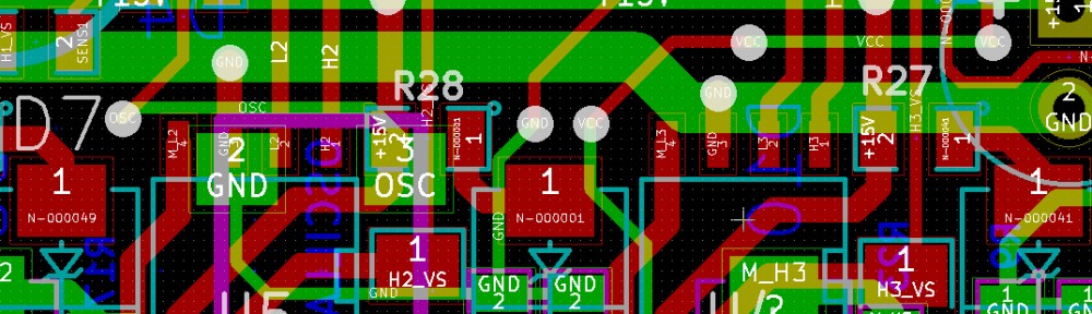
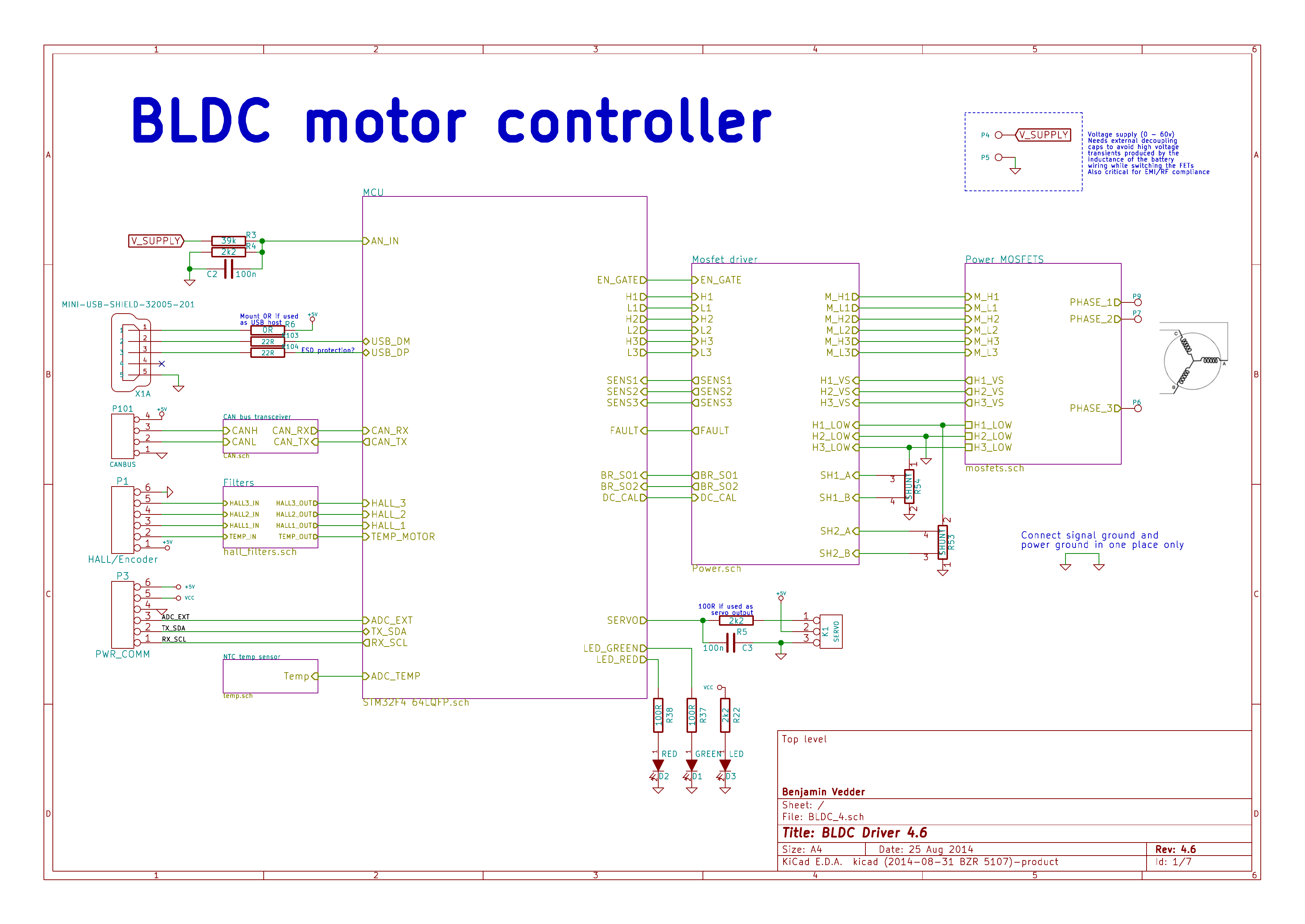
This is an overview of the schematic (download a complete PDF here):
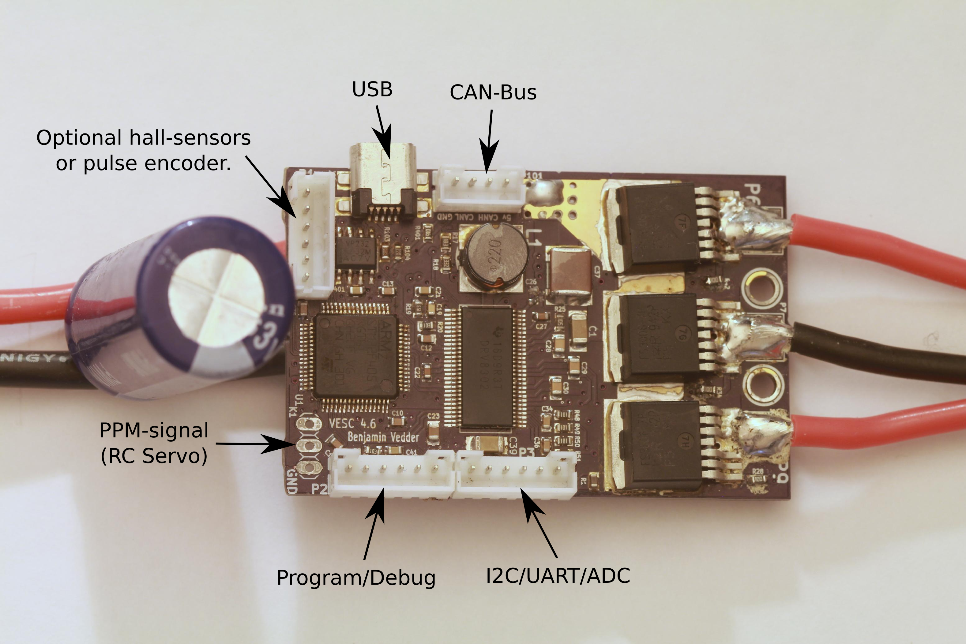
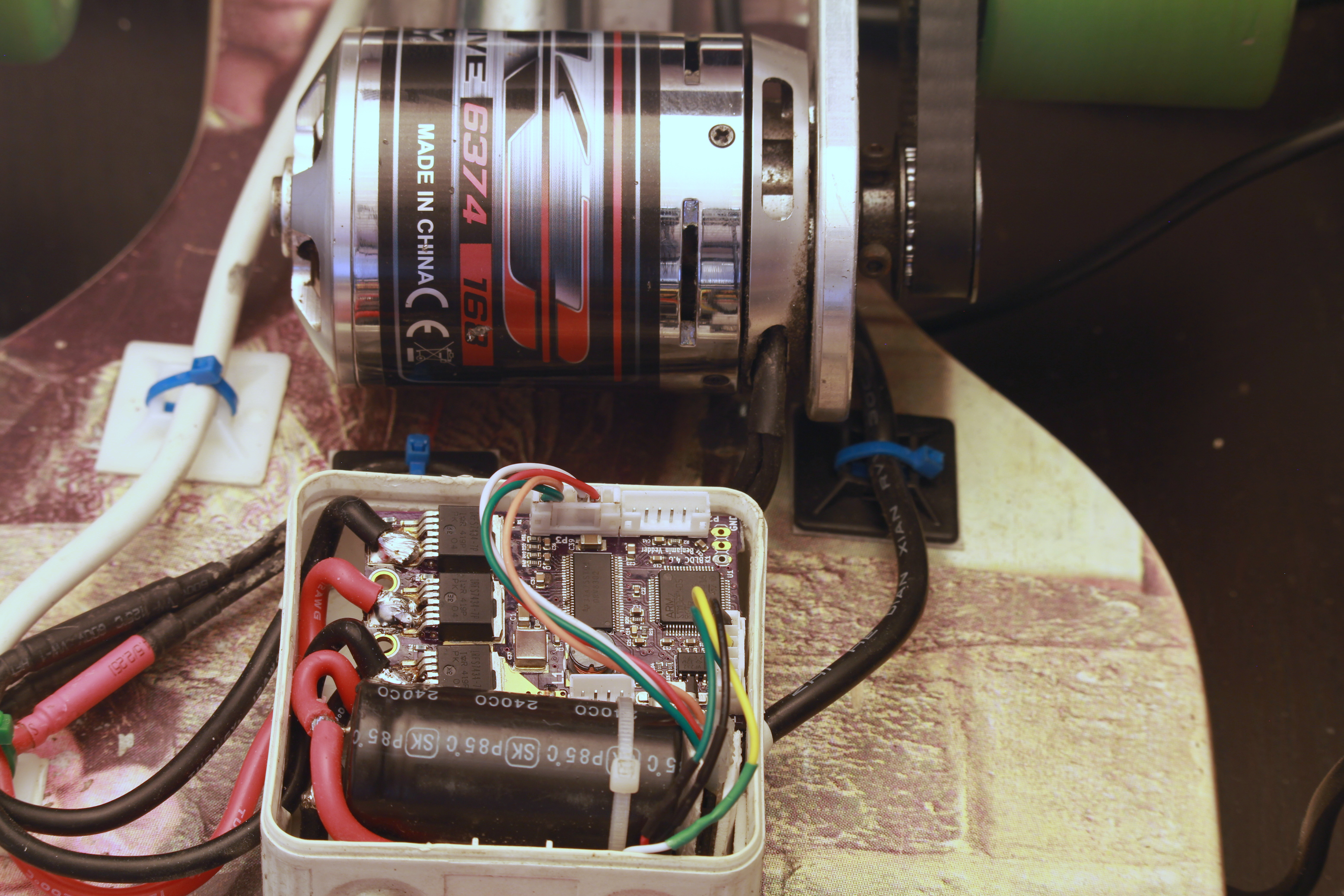
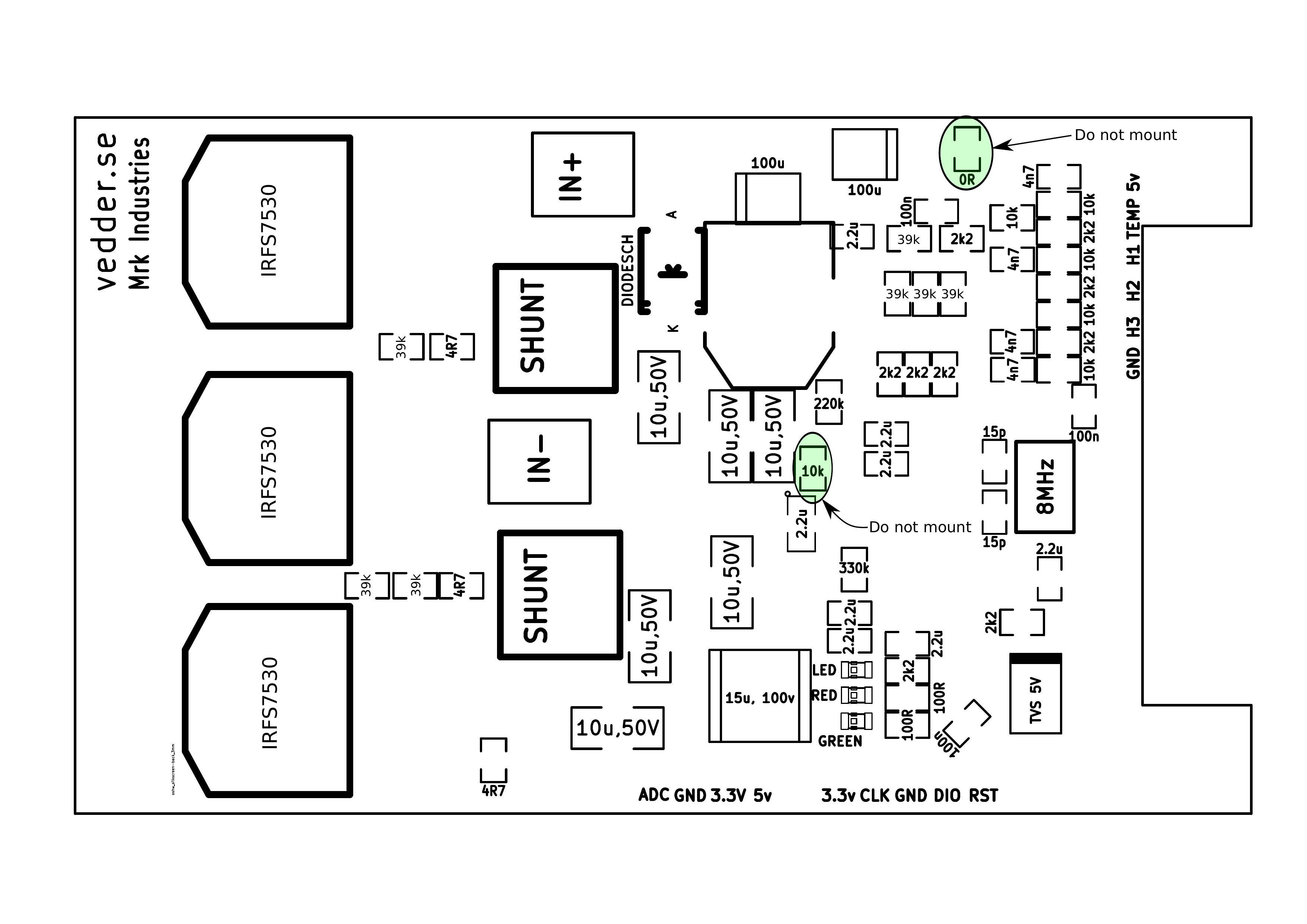
This is the front of the PCB:
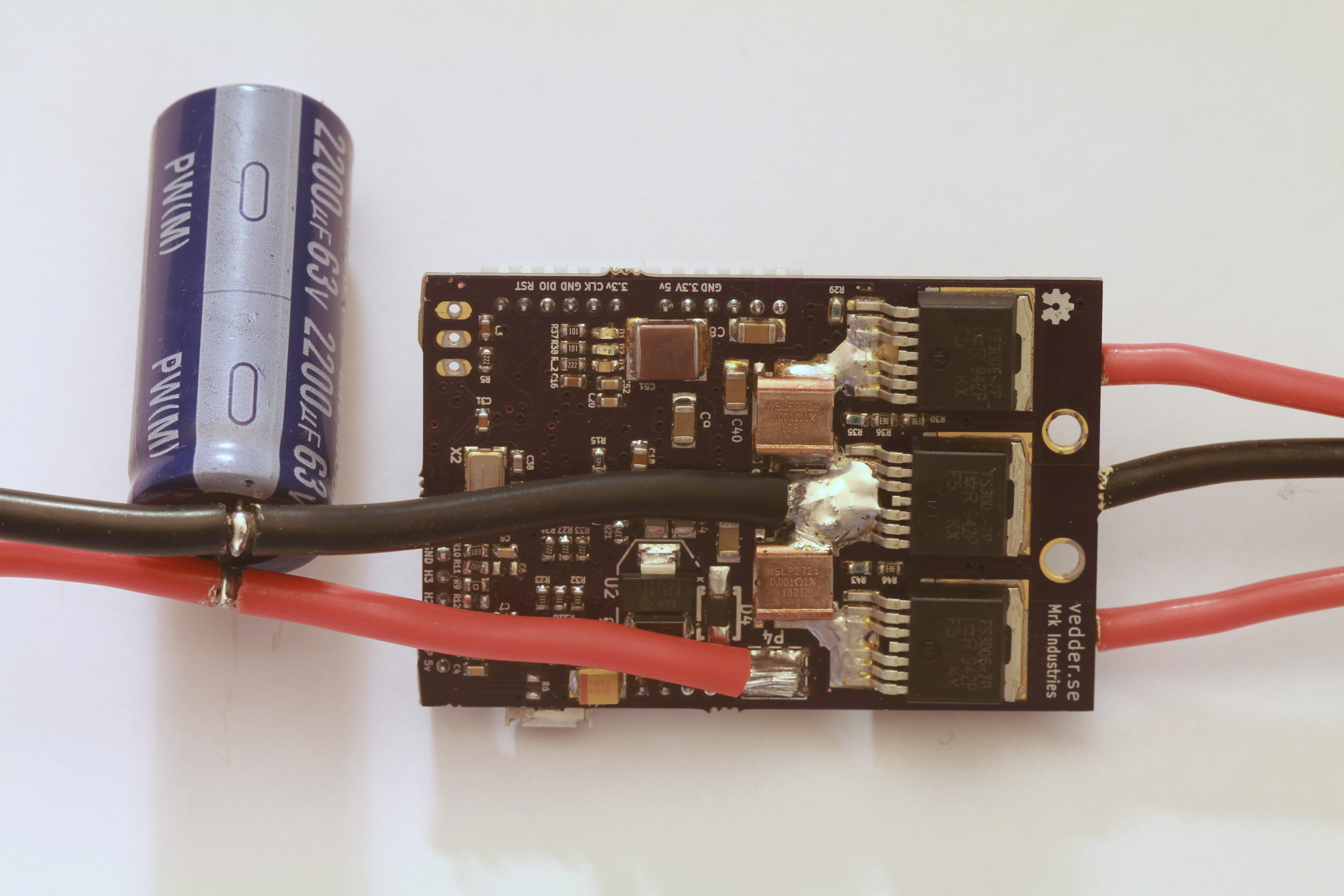
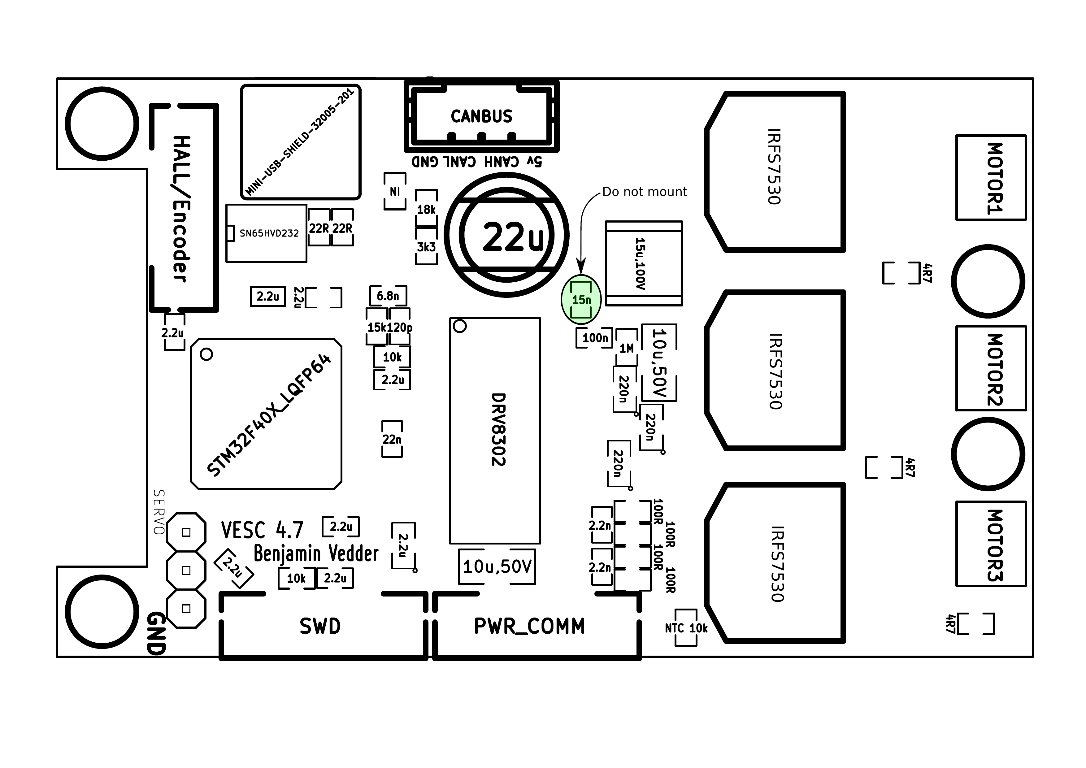
The back:
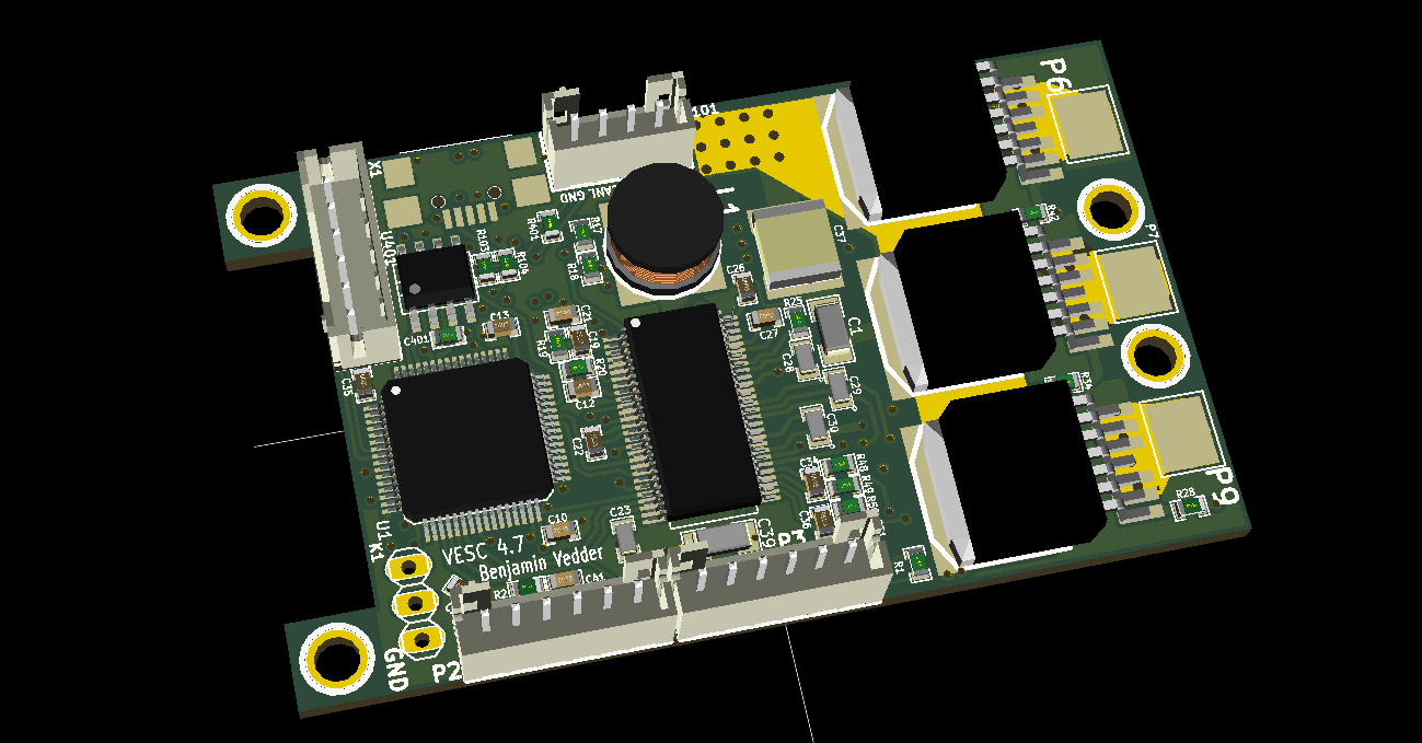
3D render from KiCad:
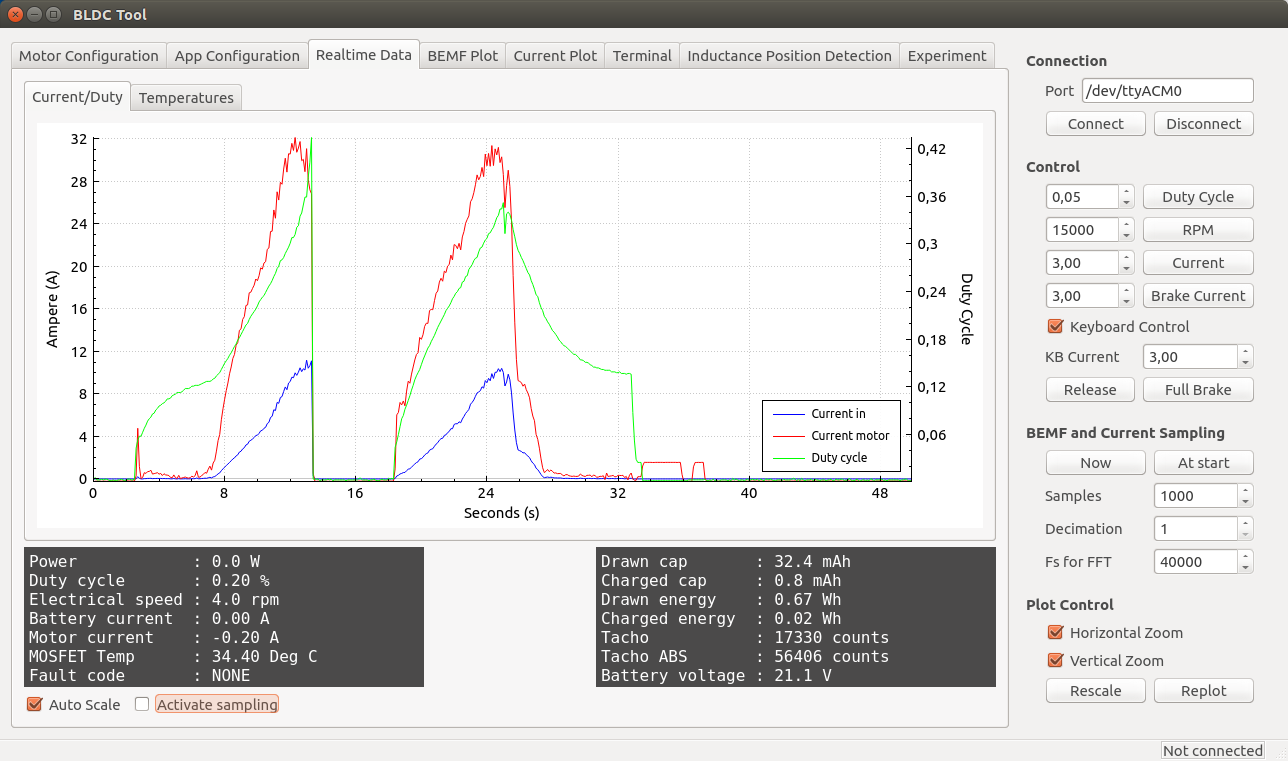
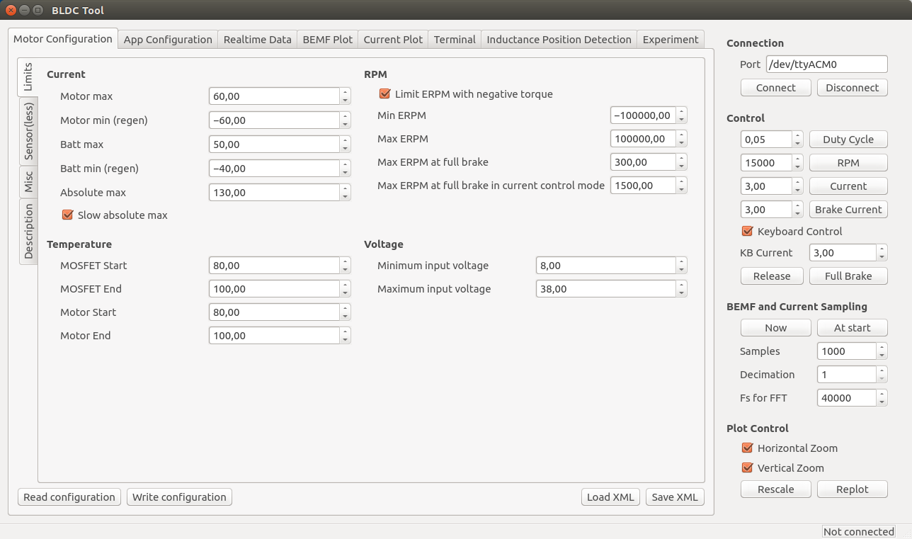
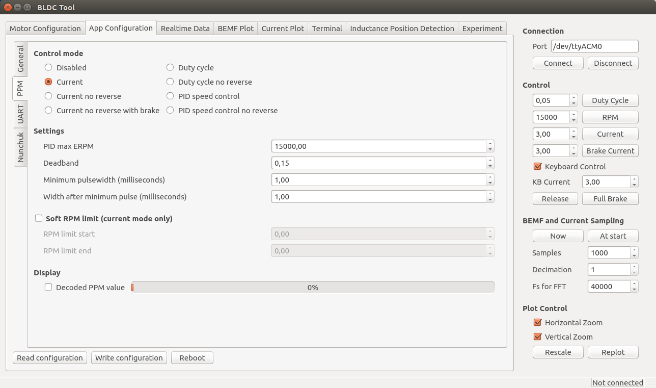
Some screenshots of the configuration GUI (BLDC Tool):
Resources
All files are on github to keep them up to date, so check these links on a regular basis:
- Hardware design
- Bill of materials
- Firmware
- Configuration GUI
- Video logger
- osx and windows builds of BLDC Tool, Video logger etc. by Jacob Bloy
Related posts
- Old post motor controller (just for reference)
- Video overlay logging
- Electric skateboard motor tutorial (KV, cells, etc.)
- Startup torque
- Hardware debugging
- Making a programmer
- Writing custom applications
- UART Communication
Forums
Because information about the VESC is scattered all over the internet and a lot of information is in email conversations with me, I have created a forum dedicated to the VESC here.
Live Chat
I have created an IRC channel on freenode where you can live chat with me and other users about VESC and my other projects. Feel free to join: http://webchat.freenode.net/?channels=vedder
Features
- The hardware and software is open source. Since there are plenty of CPU-resources left, the customization possibilities are almost endless.
- STM32F4 microcontroller.
- DRV8302 MOSFET driver / buck converter / current shunt amplifier.
- IRFS7530 MOEFETs (other FETs in the same package also fit).
- 5V 1A output for external electronics from the buck converter integrated on the DRV8302.
- Voltage: 8V – 60V (Safe for 3S to 12S LiPo).
- Current: Up to 240A for a couple of seconds or about 50A continuous depending on the temperature and air circulation around the PCB.
- Sensored and sensorless FOC wich auto-detection of all motor parameters is implemented since FW 2.3.
- Firmware based on ChibiOS/RT.
- PCB size: slightly less than 40mm x 60mm.
- Current and voltage measurement on all phases.
- Regenerative braking.
- DC motors are also supported.
- Sensored or sensorless operation.
- A GUI with lots of configuration parameters
- Adaptive PWM frequency to get as good ADC measurements as possible.
- RPM-based phase advance (or timing/field weakening).
- Good start-up torque in the sensorless mode (and obviously in the sensored mode as well).
- The motor is used as a tachometer, which is good for odometry on modified RC cars.
- Duty-cycle control, speed control or current control.
- Seamless 4-quadrant operation.
- Interface to control the motor: PPM signal (RC servo), analog, UART, I2C, USB or CAN-bus.
- Wireless wii nunchuk (Nyko Kama) control through the I2C port. This is convenient for electric skateboards.
- Consumed and regenerated amp-hour and watt-hour counting.
- Optional PPM signal output. Useful when e.g. controlling an RC car from a raspberry pi or an android device.
- The USB port uses the modem profile, so an Android device can be connected to the motor controller without rooting. Because of the servo output, the odometry and the extra ADC inputs (that can be used for sensors), this is perfect for modifying an RC car to be controlled from Android (or raspberry pi).
- Adjustable protection against
- Low input voltage
- High input voltage
- High motor current
- High input current
- High regenerative braking current (separate limits for the motor and the input)
- Rapid duty cycle changes (ramping)
- High RPM (separate limits for each direction).
- When the current limits are hit, a soft back-off strategy is used while the motor keeps running. If the current becomes way too high, the motor is switched off completely.
- The RPM limit also has a soft back-off strategy.
- Commutation works perfectly even when the speed of the motor changes rapidly. This is due to the fact that the magnetic flux is integrated after the zero crossing instead of adding a delay based on the previous speed.
- When the motor is rotating while the controller is off, the commutations and the direction are tracked. The duty-cycle to get the same speed is also calculated. This is to get a smooth start when the motor is already spinning.
- All of the hardware is ready for sensorless field-oriented control (FOC).
Writing the software is the remaining part. However, I’m not sure if FOC will have many benefits for low inductance high-speed motors besides running a bit quieter.Sensored and sensorless FOC is fully implemented since FW 2.3.
The is the ESC mounted on my electric longboard:
Sensorless startup and low-speed performance:
A short tutorial/demonstration on how to upload the firmware and get your motor running:
My electric longboard:
Video overlay logging (see a post about that here):
Hardware
The PCB is designed using KiCad. Have a look at the links under the Resources heading at the top of this page to find all files. Currently I have no assembled PCBs or kits to sell, but you can order bare PCBs from hackvana with these gerber files. Since hackvana got so many orders for my ESC, Mitch wrote a wiki page about how to order VESC boards from him. That makes it super easy to order the PCBs from him.
The components in the BOM can be ordered from mouser.com. Mouser numbers are included in the BOM as well. Make sure to order a bit extra of small capacitors and resistors in case you drop some of them and since the price doesn’t change much at all. Last I ordered, ordering 10 MOSFETs was cheaper than ordering 6 because there is a price break at 10, so have a look at the price breaks as well.
For assembling the PCBs, the following pictures are useful (the latest versions can be found on github):
Remember to put an electrolytic capacitor close to the ESC on the supply cable. How large it has to be depends on the length and inductance of the battery cables, but I usually use a 2200uF 63V capacitor.
Soldering Tips
This is the best tutorial I have seen so far. It really is as easy as it looks when done right.
- Flux is essential. Without flux, it won’t work. I use a flux pen.
- Lead-free solder is no good. It has more poisonous flux, requires more heat, gives lower quality and is difficult to handle. Don’t use lead-free solder.
- Use a flat, screwdriver-shaped tip. Don’t use a cone tip, because putting solder on the top of it is almost impossible.
- If you get bridges between smd pins, removing them is easy with a soldering wick.
- Make sure to get the alignment right for the microcontroller when soldering the first corner. If you solder multiple corners and the chip is misaligned, you have to use hot air and remove it, then clean the pads and start over.
Here is a video on the technique I use to solder the pad under the DRV8302:
I just put solder on the pad and use a hot air soldering station. Again, using leaded solder makes it easier. When soldering the DRV8302, I first solder the pad using hot air and then I solder the pins with a soldering iron. Notice that the pad under the DRV8302 must be connected for it to work, since it is the ground connection.

VESC Hardware by Benjamin Vedder is licensed under a Creative Commons Attribution-ShareAlike 4.0 International License.
Software Installation and Configuration Tutorial
This a brief tutorial on how to get everything running using a fresh install of Ubuntu 14.04. Here is a video where I do everything live to demonstrate that it isn’t that difficult. Please read all the instructions carefully to avoid most problems.
So let’s open up a terminal and get started…
Preparations
Install a toolchain to compile the firmware (for more details, have a look at this page):
sudo apt-get remove binutils-arm-none- eabi gcc-arm-none-eabi sudo add-apt-repository ppa:terry. guo/gcc- arm-embedded sudo apt-get update sudo apt-get install gcc-arm- none-eabi= 4.9.3.2015q3- 1trusty1
Install other dependencies
sudo apt-get install build-essential qt-sdk openocd git libudev-dev libqt5serialport5-dev
Add yourself to the dialout group to access the USB port of the ESC without being root:
sudo adduser $USER dialout
Uninstall modemmanager (unless you use it) to avoid a delay every time the ESC is plugged in to the USB port:
sudo apt-get remove modemmanager
Add udev rules to access the programmer without being root:
wget vedder.se/Temp/49-stlinkv2.rules
sudo mv 49-stlinkv2.rules /etc/udev/rules.d/
sudo reload udev
Log out and log back in. You should now be ready to compile the firmware, upload the firmware, compile BLDC Tool and run BLDC tool.
Download, Compile and Upload the Firmware
First, connect a programmer as described in this post. Then, download the latest firmware from github, compile and upload it:
mkdir BLDC
cd BLDC
git clone https://github.com/vedderb/bldc.git bldc-firmware
cd bldc-firmware
make upload
cd ..
Note: before running the make upload command, you should open conf_general.h and select which hardware version you are using. It is printed on the PCB. Also, 2015-01-22 I changed the voltage divider resistors to allow up to 60V to be measured by the ADC, so in that case you also have to override VIN_R1 to 39000.0 in conf_general.h.
Download, Compile and Upload the Bootloader
Again, connect a programmer as described in this post. Then, download the latest bootloader from github, compile and upload it:
mkdir BLDC
cd BLDC
git clone https://github.com/vedderb/bldc-bootloader.git bldc-bootloader
cd bldc-bootloader
make upload
cd ..
With the bootloader, BLDC Tool can be used to upgrade the firmware later.
Download, Compile and Start BLDC Tool
From the BLDC directory that you created in the previous step, type:
git clone https://github.com/vedderb/bldc-tool.git bldc-tool
cd bldc-tool
qmake -qt=qt5
make
./BLDC_Tool
You should see the following screen:
Connect the ESC to the USB port of your computer and click “Connect” in BLDC Tool. The lower right corner should now say “Connected”. If you have gotten this far, you should be ready to connect a motor and configure the ESC from BLDC Tool.
Note: If you have more than one usb-modem device in your computer (laptops often have built-in 3g modems), then you have to change ttyACM0 to the port of the ESC. To figure out which ttyACMx port the ESC got, open a terminal and type the following command right after plugging the USB cable in:
dmesg | tail
BLDC Tool can also be started by going to the bldc-tool directory with a file browser and double-clicking on “BLDC_Tool”.
Updating to the Latest Firmware
Updating to the latest firmware and the latest version of BLDC Tool is rather simple. From the bldc-firmware directory, type the following commands while the programming cable is connected to the ESC:
git pull
make upload
Note: Updating the firmware will delete the configuration of the ESC. To save it from BLDC Tool, use the “Read configuration” button and then “Save XML”. After updating the firmware, you can restore it with “Load XML” and “Write configuration”.
Also updating BLDC Tool is important and recommended at the same time as updating the firmware. In order to do that, go to the bldc-tool directory and type:
git pull
qmake
make
Now you have the latest version of the firmware and BLDC Tool. Remember to reconfigure the ESC after these changes.
Motor Configuration
Note: During the configuration, it is assumed that the USB cable is connected to the ESC and that the lower right corner of BLDC Tool says “Connected”.
The first thing to do in the “Motor Configuration” tab is to click “Read configuration” while the ESC is connected to get the current configuration. After that, click “Load XML” and look for a configuration that is the same as or similar to your motor in the “mc_configurations” folder included with BLDC Tool. If you find exactly your motor, you don’t have to change anything unless you want to tweak some parameters for your application.
Note: Even if you load an XML configuration file, use “Read configuration” first anyway because the XML might not contain all parameters. The missing parameters will become blank and can mess with things. Soon I will make sure that sane default parameters are loaded, but I haven’t done that yet.
Sensorless Motor Parameters
Since this ESC uses uncommon techniques to commutate the motor in order to get good low-speed performance without sensors, it is important to set correct motor-dependent parameters in the sensor(less) tab. Otherwise, the motor will run poorly or not at all.
This is what the Sensor(less) configuration page currently looks like (I will probably add more auto-detect options soon):
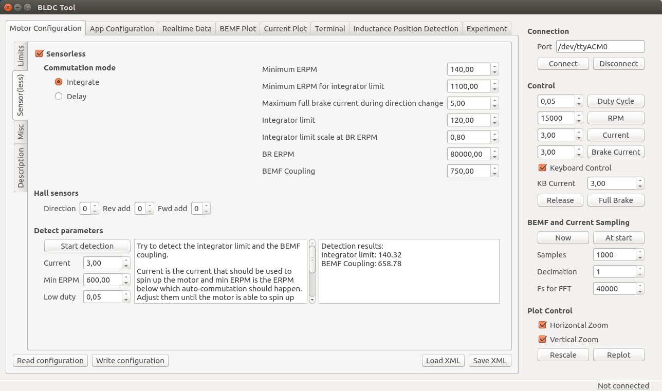
The important motor-dependent parameters are “Integrator limit” and “BEMF Coupling”, and they can be measured with the detection part. I will make a video showing this for several different motors soon, but until then you can try to follow these instructions:
- Connect the motor without any load and make sure that it can spin up freely.
- Make sure that no other input such as PPM is used. If it is, it will stop the motor immediately when the detection tries to start it and the detection will fail.
- Click the “Start detection” button. The motor should spin up, release throttle and then run slowly for a moment.
- If the motor doesn’t spin up properly, Adjust “Current” and “Min ERPM” until it does. In general, small motors should have lower current and higher ERPM and larger motors the other way around. Current usually is in the range 1A to 6A and min ERPM usually is in the range 300 to 1200.
- If spinning up works but running slowly afterwards doesn’t (the motor just stutters), try increasing “Low duty” to 0.1 or so. Increasing low duty will make it easier for the motor to run slowly during the test, but the result will become less accurate.
- Manually put the obtained values into the boxes. I usually round “integrator limit” down to the closest multiple of 5 and “BEMF Coupling” down to the closest multiple of 50. Having them slightly lower than the detection result is good in most cases, so that’s why I round them downwards like that. Getting these parameters perfectly right is not too critical though.
- The next parameters to adjust are “Min ERPM” and “Min ERPM for integrator limit”.
- What they should be depends on the application and is in most cases not too important, but in general lowering them will work better if the load has much inertia. I have Min ERPM around 200 and Min ERPM for integrator limit around 1000 for all my applications.
- You can probably keep the same parameters I have, but if you want to tweak your startup you can experiment with them.
- It is important that “Min ERPM” always is lower than “Max ERPM at full brake” and “Max ERPM at full brake in current control mode” on the “Limits” page.
- Commutation mode should always be “Integrate”.
- The other parameters are for RPM-based timing advance and some other things that aren’t necessary to adjust in the normal case, so I won’t explain them here yet.
For small low-inductance high-speed motors, the delay commutation mode can be used in case the integrate mode does not work. It does not require many parameters, just the minimum RPM which usually can be around 1500. I haven’t tested this mode much, but it is more or less how most hobby ESCs work (which is why it doesn’t require so many motor-specific parameters). Currently it does not support adjustable timing, but I will implement that in a few days since it is quite easy.
Phase advance (other terms: timing adjustment, field weakening)
To compensate for the current lagging behind the voltage at high speeds because of inductance or to get a bit higher top speed at the expense of some efficiency and torque, phase advance can be used. It is implemented in a speed-dependent way so that the motor gets more phase advance the faster it spins. It is implemented this way because having phase advance at low speeds does not give any improvements at all as far as I know, so the best way is to increase the effect as the motor increases its speed. BR ERPM is the electrical RPM of the motor at which the set phase advance is used, and Integrator limit scale at BR ERPM (will rename this option soon…) is the amount of phase advance to use. Setting it to 1.0 gives no phase advance and setting it to 0.0 gives 30 degrees (maximum) phase advance. The set phase advance will be mapped linearly between 0 ERPM and BR ERPM. If you don’t know what this is, you can leave the default options since it is not that important.
Motor
Current, temperature, RPM and voltage-limits can be configured depending on your application.
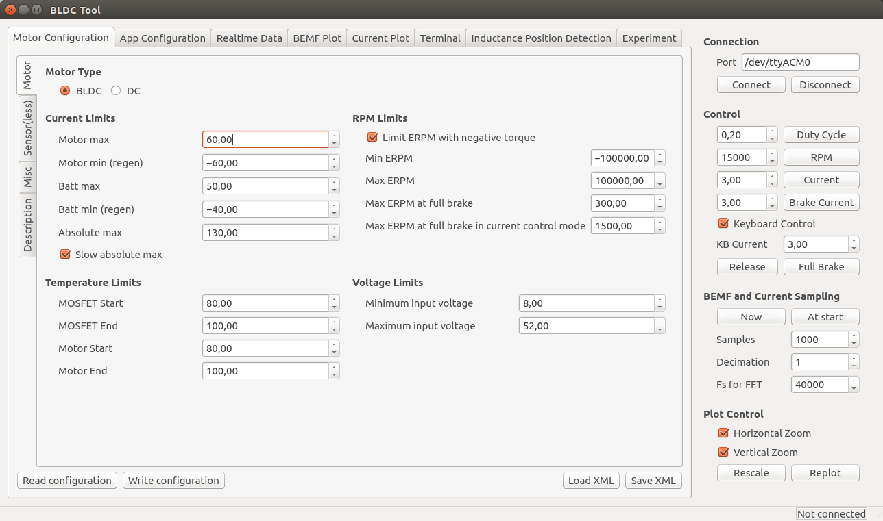
Note: These limits are not foolproof. If you set them too high, you can damage the ESC and/or the motor.
- Current
- Separate limits for acceleration and braking current.
- Separate limits for motor and battery currents.
- “Absolute max” is checked in every PWM switching cycle and used in case the soft back-off strategy for the other limits doesn’t work. I usually set it way higher than the other limits because soft back-off is preferred rather than switching off the motor with a fault code, but it should never be higher than 150A.
- The “Slow absolute max” box will make sure that a filtered version of the maximum current limit is used. This is useful if there is much noise and that fault code kicks in all the time. I usually have it ticked.
- Temperature
- At the “Start” temperature, the current will become more and more limited linearly until the “End” temperature, where the output is switched off completely. Setting them about 20 degrees apart will make the ESC slowly decrease the maximum output current as it gets too warm instead of abruptly switching everything off.
- MOSFET temps (on the ESC) are implemented and working, but motor temps are not implemented yet. They will require an external temperature sensor in the motor. The software implementation is rather simple since I can just copy most of the MOSFET temperature limit code.
- RPM
- Max and Min ERPM are hard RPM limits. It is preferable to use the soft application RPM limits instead if possible.
- “Max ERPM at full brake” (should change the name…) is the highest opposing RPM at which a direction change is allowed. Setting this too high will cause cogging when moving in one direction and giving high throttle in the other direction. On my longboard I have it at 300 and my RC car has it a bit higher.
- “Max ERPM at full brake in CC mode” is the highest RPM at which applying full brake by shorting all the motor windings is allowed. Setting this value too high can cause much mechanical stress in some circumstances. I have it at 1500 for all my applications.
- Voltage
- The minimum and maximum input voltage.
- NOTE: I changed the voltage dividers in hardware 2015-01-22. If you have built the PCB before that, the maximum voltage can’t be more than 52V. The difference is whether the PCB has 33k or 39k resistors. 33k means that maximum 52V can be measured. The latest PCBs (with 39k resistors) can measure 60V, but you should have some margin on your supply voltage to be safe. You can of course replace all 33k resistors with 39k and measure up to 60V.
Once the ESC is configured for your motor, you can use the up and down arrow keys to run the motor forwards or reverse in current control mote, or the right and left arrow keys to run the motor forwards and reverse in duty cycle mode. The buttons in the right-hand side of the GUI can also be used.
Misc
Here are the rest of the motor configuration parameters. You probably want to experiment with Startup boost if you are using current control. The rest of the parameters can be left as their default values unless you have some specific reason to change them.
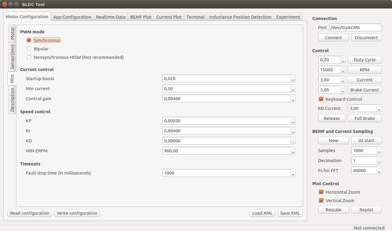
- PWM mode
- Synchronous is recommended and the best choice for a majority of all motors. If you have some weird motor, Bipolar could work better, but it probably won’t. Nonsynchronous is only for experimentation and can kill the ESC if you are unlucky.
- Current control
- Startup boost is the minimum duty cycle to use when using current control. If the motor is to weak when you are just starting, you can increase this parameter a bit until it feels right. The range is 0.0 to 1.0, where 1.0 is full throttle (which you shouldn’t use.). A sane range is up to 0.15 or so.
- Min current is the minimum allowed current. There should be no reason to change this, so leave it at the default value.
- Control gain is the gain used by the current controller. Increasing it makes the current response faster, but also increases the risk of getting an unstable system where the ESC can get damaged. Only change this if you know what you are doing.
- Speed control
- The PID parameters for the speed controller. Only change them if you know what you are doing.
- Timeouts
- Fault stop time is the amount of milliseconds that the ESC should be completely switched of when a fault code arises. After that time, it will switch on and try to listen for commands again.
Application Configuration
First, click “Read configuration” to get the current configuration from the ESC. After that, select which application to use and configure that application.

- Controller ID is the ID of this VESC. If multiple VESCs are connected over CAN-bus, they must have different IDs.
- Send status over CAN has to be enabled to make other VESCs aware of this VESC and some of its current state. It should be enabled for all slave VESCs when connecting multiple VESCs over CAN-bus.
- Changing application requires a reboot. There is a button for that. After a reboot, you have to click connect again.
- Timeout is the amount of milliseconds after which the motor should be shut off in case the control signal is missing.
- “Brake current to use…” can be set to make the motor brake with a certain current when a timeout occurs instead of just releasing it.
PPM
The signal that a normal RC receiver outputs is a PPM signal, so this can be used when connecting an RC receiver to the servo port.
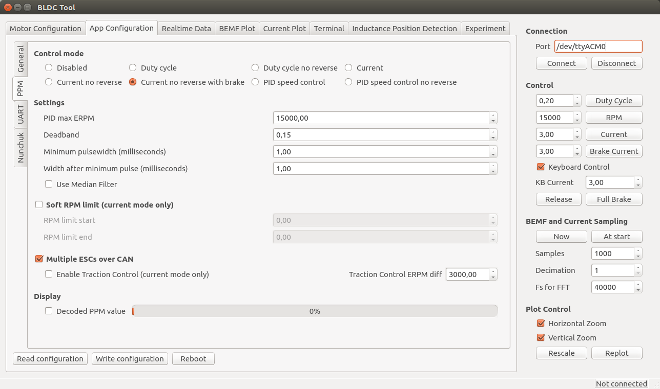
- Control mode
- Disabled: Nothing at all, motor is off.
- Current: Torque control. This is what I prefer since it feels most natural. I haven’t seen hobby ESCs that have current control.
- Current no reverse: Save as above, but no reverse function. Note that centring the now will give half throttle.
- Current no reverse with brake: No reverse, but centre is zero torque. Reversing will brake, but not change motor direction.
- Duty cycle: Duty cycle or voltage control. What most hobby ESCs use.
- PID speed control: The throttle command is intepreted as a speed set command and closed-loop control is used to maintain that speed. “PID max ERPM” sets what max throttle should be interpreted as.
- Settings
- Deadband: how much span in the centre of the throttle should be ignored.
- Minimum and maximum pulsewidth: The timing interpretation of the PPM signal can be adjusted in case your receiver doesn’t follow the specification or it you have some other reason to change it. Setting “Control mode” to “Disabled” and ticking display decoded PPM value is useful when adjusting these.
- Use Median Filter enables a filter that is very useful when there are glitches on the PPM signal. If you have a quadcopter application, you should disable the filter and make sure that there are no glitches since a filter introduces some delay.
- Soft RPM limit.
- Speed limit that can be used in current control mode. Setting the start and end limits a bit apart will result in a soft torque decay when approaching the speed limit.
- Multiple ESCs over CAN can be enabled to connect several VESCs over CAN bus. All VESCs must have different Controller ID and the slave VESCs must have Send status over CAN enabled (see the general tab under app configuration). The slave VESCs don’t need to have any application enabled since they will just be listening for CAN commands. Traction control can also be enabled, which reduces the torque on motors that spin faster than the slowest motor proportional to their speed difference. To connect VESCs over CAN-bus, connect the CANH and CANL signals between them. DO NOT connect 5v and GND because that is likely to cause ground loops which can reset and/or kill the VESCs.
Nunchuk
The Nyko Kama wireless nunchuk can also be used to control the ESC. Note that not all nunchuks for the nintendo wii will work, because they slightly differently.
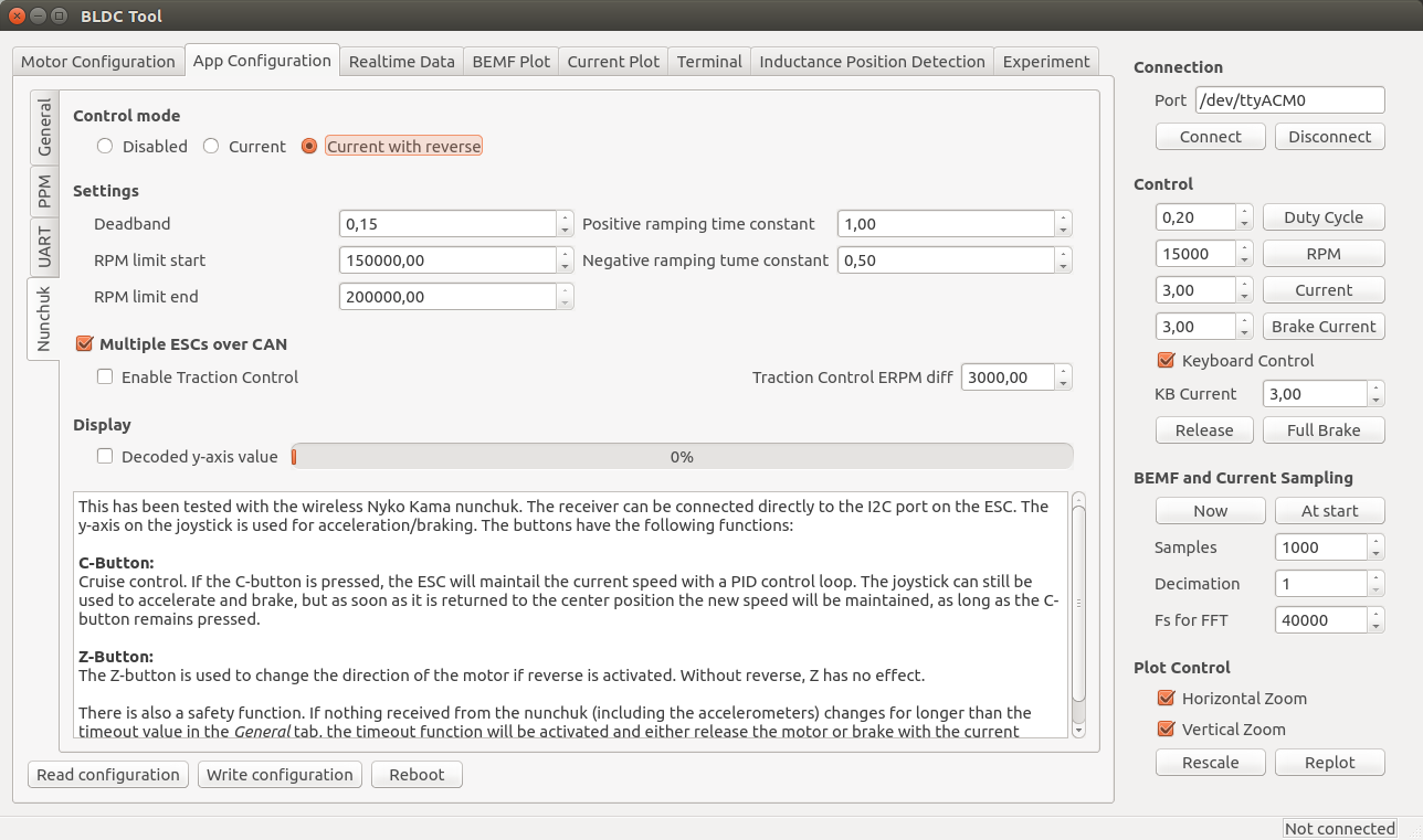
- Control mode
- Disabled or current control with or without reverse. If reverse is used, the Z button is used to toggle a direction change.
- Settings
- Deadband: The span in the centre of the throttle that should be ignored.
- RPM limits: Limit the electrical RPM of the motor. The start value is the point where the torque should start decreasing and the end value is the point where the output will be switched off. Setting them slightly apart will give a soft RPM limit. Setting them very high will disable the RPM limit.
- Ramping time constants: How fast the throttle command should be followed, in seconds.
- Multiple ESCs over CAN can be enabled to connect several VESCs over CAN bus. All VESCs must have different Controller ID and the slave VESCs must have Send status over CAN enabled (see the general tab under app configuration). The slave VESCs don’t need to have any application enabled since they will just be listening for CAN commands. Traction control can also be enabled, which reduces the torque on motors that spin faster than the slowest motor proportional to their speed difference. To connect VESCs over CAN-bus, connect the CANH and CANL signals between them. DO NOT connect 5v and GND because that is likely to cause ground loops which can reset and/or kill the VESCs.
A video where I test this:
Realtime Data Display
Use the “Realtime Data” tab to display realtime information from the ESC. Make sure that the “Activate sampling” box is checked.
Common Problems and Solutions
As I encounter different problems, I will put them here together with possible solutions for reference.
Uploading the firmware does not work.
- Make sure that you have followed all steps in the tutorial, including adding udev rules to access the programmer without being root.
- Don’t use a too long cable for the SWD connector.
- Make sure that you have a working programmer. I got one from ebay that didn’t work at all and one that died quickly. Otherwise they have been reliable though.
A DRV8302 fault code appears as soon as the motor starts.
- Make sure that R16 is not mounted (see the comment in the schematic).
Connecting to VESC via BLDC Tool does not work.
- Run dmesg to see which ttyACMx port gets assigned to VESC when plugging in the mini-usb cable.
- Make sure that the mini-usb cable is plugged in and that power is connected to VESC. Connecting BLDC Tool is not done via the SWD programmer, but via the mini-usb port.
- If you are using a different usb-connector than the one from the BOM, make sure that the order of the pins is correct. The connector in the BOM is upside-down, so a connector that isn’t will have all the pins mirrored.
My motor is not running properly.
- Make sure that you have configured VESC for your motor as described above. VESC is not plug-and-play and needs an individual configuration for each motor. Without the configuration, the motor will run poorly or not at all. Read the instructions carefully.
Is there a way to “boost” the startup of my motor when using current control?
- Yes, the Startup boost option under Motor Configuration > Misc tab in BLDC Tool can be adjusted as described above.
Update: I have ordered assembled VESCs, some of them are for sale
Update about this update: There are no assembled ESCs left. However, If you are interested in assembled VESCs you can still send me an email as described below so that I can put you on my extra list. If someone changes their mind or if there are other problems, I can send you VESCs that get left.
I have ordered 100 assembled VESCs and they will arrive this or next week. I don’t need all of them, so I will sell some of them for 115€ + shipping. Worldwide shipping with tracking is 20€ per order (which can contain more than one VESC). Shipping within Sweden is less expensive and I will update this post as soon as I know the price. You can contact me by email if you are interested (benjamin at vedder.se). Tell me how many VESCs you’d like and your address, and I will reply with an email that confirms that I have put you in my list. Later, when I have figured out how to accept payments, I will send another email with information about how to do that. As soon as I receive your payment, I will ship the VESC(s) to you and send an email with tracking information
I will update this information in the coming days, so make sure to check if there are updates.

Awesome projet! Awesome, awesome and awesome!
How long have you been working on this?
Thanks!
The past four years or so I have been working with motor control in my spare time. 2014 I spent almost all of my spare time on this motor controller.
Hey ho! This sounds so awesome! Thank you for sharing your knowledge. Any plans on selling finished units or kits in the near future? What would you estimate the build costs for a single ESC to be if I was to build one? And is there any way to run the software from a computer running windows?
I have asked for a quote on some pre-assembled PCBs. If you can do the assemble yourself, the PCB and all the components are about 100€. I will post some updates when I know more about the pre-assembled ESCs.
To run the software on windows you would have to port about 700 lines of serial-port code. I haven’t used windows for 10 year and I don’t like microsoft so I can’t do or support that, but since the code is open you are free to do so. I hope this ESC will be another good reason to run some Linux-based distro though.
There is a windows version working as well as a OS X version.
Hopfuly I can keep this link up for a while https://docs.google.com/folderview?id=0Bym9XrdeViekfkRETmRndENkcVpySW5sWjIzOWdrLThCY01HY3BPOXpqYVRHUlQxS0R5ZlU&usp=docslist_api
Hey,
is there a chance to get allready build software versions? i am also using windows and have no experiences with linux.
Cheers,
Alex
Even if I build the software on linux, it won’t run on windows. To build it on windows, you have to remove the linux dependencies and replace them with the equivalent windows ones. Currently, the only dependency outside Qt are about 700 lines of code to interface with the usb-serial port. I think the most recent versions of Qt have some platform-independent code that can be used to interface with the usb-serial port, but then I will lose the low-level control that I currently have. Also, I don’t have any computer running windows, I haven’t used windows for 10 years and I don’t know how to develop software using windows. Further, as I mentioned, I don’t like microsoft for many reasons, so my motivation for spending many days trying to make a windows build is zero. For me it also is a good thing that my ESC is another good reason to run some linux distribution.
i allready started to get the right distro and will start a partition with linux. would it never the less be possible to get build linux files?
Alex
I could make a pre-compiled version of bldc-tool, maybe even a deb-package for debian-based distros such as Ubuntu. Which distro are you running? Building bldc tool from source is not too bad. If you have something debian-based such as Debian, Ubuntu, Kubuntu, Mint etc, you can simply run the following commands from a terminal:
sudo adduser $USER dialout

sudo apt-get remove modemmanager

sudo apt-get install build-essential qt-sdk git

git clone https://github.com/vedderb/bldc-tool.git bldc-tool

cd bldc-tool

qmake

make
This will install all dependencies, download and build BLDC Tool. After that, you can log out, log in and double-click on BLDC_Tool to start it.
Hey,
i will try my first start with ubuntu. do you reccomend a certain version or should i just try the newest?
And to make it easier, could you also provide a build version of the bldc code? i think that would make things much easier and people dont have to mess around with setting up the toolchain.
I am really excited, to test it 🙂
Alex
I’m using Ubuntu 14.04, which is a long term support release. I don’t see any benefits running 14.10 and it will only be supported for 9 months, so I recommend 14.04.
I can upload the compiled firmware to github. To do that and keep the files up to date, I can make a script that builds the binaries for the different hardware versions that I can run before each commit. Installing the toolchain and building everything is not too difficult either, just paste a few commands into the terminal as described above.
https://docs.google.com/folderview?id=0Bym9XrdeViekfkRETmRndENkcVpySW5sWjIzOWdrLThCY01HY3BPOXpqYVRHUlQxS0R5ZlU&usp=docslist_api
Windows and OS X BLDC tool and video logger.
Great stuff.
We work with a chinese MFG, and I think that the assembly will have a tooling cost of about $500. At 20 pcs its $25 per board in assembly, with more boards it gets cheaper. Ping me if that suits you.
Do I hear kickstarter?…
That sounds awesome! I have asked PCB-train for a quote, but haven’t received a reply yet. Based on the emails I have gotten so far, we could probably order more than 20 PCBs in the first batch for testing.
Before starting something like kickstarter or indiegogo I would like to do more testing, especially on higher voltages and currents and also have other people do some testing. I have sent two ESCs to Austin and Dexter from endless sphere who are testing them on electric skateboards, which are among the most rough environments the ESCs can be used in. I also have parts on their way for a dual-motor electric longboard with 12s (50.4V) LiPo batteries and two motors. If the PCBs are working well for Austin and Dexter and my new longboard works well with 12s, I would be more confident to use crowd funding.
I will let you know when I have asked around and tested my 12S longboard.
Nice Project!
One question: did u think about an active cooling ?
I mean the 5v coolin fan for the mosfets just like on CPUs.
Adding a 5V cooling fan will help a lot. If you can fit the fan on your setup, you can simply connect it to the 5V output.
I think that the software should be improved, before any serial production is started.
Motor detection as it is now can damage the ESC in some cases.
I managed to damage 3 ESCs (failed driver + mcu) when I tried to run
small high speed motor with high cogging (HET RC 1W-40).
I was able to repair one ESC, one is not working OK even tough I replaced the MCU and DRV8302 (bldc tool reports high duty cylce even at no speed/idle).
Larger motors seem to work fine for now.
is it that motor?
http://www.effluxrc.com/HET-1W-40-3300kv-Motor-HET1W40.htm
By just reading the specifications (some units are missing), I don’t think that motor will work well with my ESC. Since the motor has 3300 kv and 6 poles, the electrical RPM with a fully charged 6s lipo will be: 3300 * 4.2 * 6 * 3 = 249480, which at 35kHz switching frequency gives less than two samples per PWM cycle. This is a lot higher than the current switching frequency allows, especially at low duty cycles. Computation-wise the ESC can go up to about 60kHz (more if I optimize it), but the FETs are too difficult to drive for the DRV8302 at that frequency.
The fact that the motor has 6.2 mOhm winding resistance together with the high electrical speed implies that is has very low inductance. This means that when doing the detection at low initial switching frequency, the current will probably drop to zero before the sampling is done meaning that there is no current feedback and the current can rise until something breaks; which is probably what happened. A motor like that will almost affect the ESC in the same way as shorting the output wires and trying to run the motor. By ignoring the current (cheap ESCs don’t care about current), turning up the lowest switching frequency and using no more than a 3S LiPo, that motor could probably run, but most of the protection features won’t work. Maybe I can move the ADC sampling points around to make that motor run, but I would have to test that myself. So far this is the most extreme motor I have seen anywhere, so these problems will be more of an exception than the common case.
What I can do with the detect function would be to add a few test PWM cycles with current sampling during the ON-time to determine if the motor is too extreme or if there is a short in order to prevent damage to the ESC.
Another thing:
One easy way to prevent damage is to use a lab power supply with no more than 12V and not too big capacitors when first trying a new motor. If that works, you can first turn up the voltage, try again and then try it with a battery.
Yes that is the right motor. During the motor detection phase the motor stopped working (controller was returning DRV8302 fault and the red led was blinking three times). With some motors I have the detection function seems very rough – it also does not work on a power supply because of the high startup current needed (some motors have high cogging torque).
The following motors were tested (all on 4S):
1. Feigao 540XL, 2000rpm/V (slotless motor, 2 poles), detection OK, running OK
2. Leopard LBP3674/3D, 2200rpm/V, detection little harder (had to repeat few times), runing OK
3. Mega ACn 22/20/2 (6 poles, 13.1 mOhm p2p resistance, 3.8uH p2p inductance) – detection not realy easy, running OK, except had to limit max erpm to around 50k otherwise motor spun up to max rpm and control did not work anymore (PPM mode), did not test with latest firmware
4. HET RC 1W/40 (6 pole, really high cogging torque) – not running, damaged controllers, this kind
of motor has limited usage fields (high speed pylons, RC boat racing). I could probably send you
the motor if you would like to make the detection more reliable (less issues if someone puts a similar motor on the controller).
5. Large BLDC motor (2.5kg, 200rpm/V, 35mOhm p2p resistance, 100uH p2p inductance) – detection OK, running OK
The current limiting feature (battery&phase) is what makes this ESC different from all other similar controllers on the market. That is the reason why I decided to make one.
Few more questions:
a) What is the reccomended size of the “DC Link” capacitor – I see on one picture that you use 2200uF
is size more important or better to use low esr capacitors ?
b) Can changing the min pwm frequency (3kHz -> 8kHz) damage something ? I feel that the
startup of the motors is not really best on some of my motors, would this make it better ?
c) I have one controller that is not working ok (the bldc-tool reports high duty cylce at idle (~0.9).
When I try to start the motor, the controller returns overcurrent fault – I’ve replaced the mcu and
driver, the mosfet seem OK (measured resistance between phases around 70k). What else to check ?
I haven’t experimented much with high-speed inrunners, but in general they are different to start without load since the rotor hardly has any inertia and they don’t have much of the coupling factor that the low-speed performance relies on.
a) That depends on the inductance of the supply. If you have long battery wires for example you need more capacitance. Low ESR is always better to avoid losses, but the highest frequency spikes are taken care of by the ceramic capacitors on the PCB.
b) It shouldn’t damage anything, but startup will become worse for large outrunners (and most other motors I have tested). Having low frequency at low duty cycles makes sampling the voltages more accurate since it is done in the on-time, but also causes more current ripple for low-inductance motors. For my outrunners, 3 khz (the lowest frequency that doesn’t cause a timer overflow) has been working best to get a smooth start, but for low inductance motors it might be better to trade some adc sample quality for lower ripple. However, experimenting with the minimum ERPM and the minimum ERPM for integrator limit in the sensorless tab should give better results for getting a smooth start. The best settings to start the motor smoothly on the bench are not the same as for starting the motor smoothly under load since the rotor in an inrunner has very low inertia without load. I have spent lots of efforts on getting good startup torque under full load, but the motors you are using are ones that I haven’t experimented much with.
c) I have managed to break R48 to R51 some times and the voltage regulator. Also check the gate resistors.
It seems that one of the resistors on the phase voltage sense divider is reading low. R33 is reading around 2k even after I replaced the resistor.
R33 should be 2.2k, so that is not much difference. If you read the resistance while the resistor is mounted, the rest of the circuit will affect the reading.
It would be nice if you could send me the HET RC 1W/40 motor so I can test it.
What kind of power supply do you have? I have a 10A supply and I didn’t have any issues. Even a 5A supply should work for testing motors without load.
I found the error on the controller – there was a very small hard to notice solder bridge on the mcu. It was working OK until the 3.3V regulator died.
The PSU that I have is not able to deliver more than 1A@20V. Yes with more powerful psu the detection should be OK.
I will send you the motor – check your e-mail, so you can give me your adress.
I have asked some colleague at work to check the gate driving on an osciloscope.
The snapshots are on the following links:
http://shrani.si/f/1Q/2i/QsXr5c7/first-motor.jpg
http://shrani.si/f/S/Zb/2zSPv3gl/first-motor1.jpg
http://shrani.si/f/1P/kg/2gem9g2p/second-motor1.jpg
First motor is the Leopard, second the Feigao.
Red trace is showing the gate voltage on the high side mosfet. As far a I know is that this not realy good. I see on one of your pictures that you have increased the gate resistors to 10 ohm on the high side.
Thanks! I will reply to the email in a minute.
The photo with the 10 ohm gate resistors actually has two 10 ohm resistors on top of each other (giving 5 ohm) because I didn’t have more 4.7ohm resistors when I soldered them.
Your pictures look like you didn’t use the correct reference voltage when you measured the high side gates. Putting the ground clamp of the scope on gnd doesn’t work because the high side is floating around relative to ground. You have to put the ground clamp of the oscilloscope to the motor terminal output of the half bridge that you measure the high side gate of (which also is the reason why using high-side n-channel FETs is a bit tricky). When doing that, you have to make sure that your power supply is isolated and that no programmer or USB cable is connected to the ESC, otherwise you will short everything via the ground of the oscilloscope. I usually measure the high-side gates with only a battery and nothing else connected.
I just measured one high-side gate of my controller with 4.7-ohm resistors:
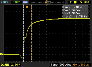
In my picture it looks fine and there is no ringing. You can try to make the measurement again like I described. If it doesn’t look fine, there is probably something wrong with your PCB.
I want to utilise the full potential of your ESC for my electric bike.
Beside changing the voltage divider, is there any other modifications to do in order to use 58V ? Maybe the code the FET seem ok.
You have done a wonderful work, congratulations.
Michel
You have to change a resistor value define in the software, but that is simple. I will make something in conf_general so that can be done. What you also should do is replace the 50V 10uF caps with 100V caps, such as these:
http://se.mouser.com/ProductDetail/AVX/12061Z475MAT2A/?qs=sGAEpiMZZMs0AnBnWHyRQMqfda103KBdRa%252bv69sOqWA%3d
The 50V ceramic caps will probably survive 58V without problems, but their capacitance drops a lot at high voltate. At just the rated voltage, they can loose 70% of their rated capacitance.
I haven’t tested with 58V yet, so I don’t know how reliably it will be at that voltage. I was planning to never run on more than 12S LiPo (50.4V on full charge) to get some safety margin on the voltage, but maybe 58V also works.
The DRV chip stops at 60V.
in my experience the margins on this type of chip is small. So when you say 58V, is that really 58V? If my guess that you’re using 14*4.2V is correct, then it is already 58.8V, only 1.2V margin left. With inductance or “ESR” issues with the battery while braking, the voltage can easily go past the 60V where damage might occur.
Also the current mosfets are 60V, again: in my experience: there is little margin, they blow at less than 70V.
I just finished soldering 2 of the 4.0 esc’s today. Damn you move fast – you already advanced to 4.6 😉
The programmer will hopefully show up this week so I can hook up the esc to various motors I have lying around/built into different projects.
You rock!
Is part # 19 on the bill of materials list correct? The description says 220n 25v but mouser lists it as 50v 0.22uf.
220n is the same as 0.22uf, but with another prefix. Having a higher voltage rating for capacitors is always better, so that part is fine.
awesome thanks!
Hi Ben,
Very impressive work, just wonder is it possible for me to change the MCU to a lower speed one and a lower current MOSFET? as I am just a student do not have that much spare money on top IC. Will this affect the system? I will only use 5065 motor should within the power rating
Frank
Hi Frank,
you can change the mosfets to any version in the same package. There are some 40V fets available for half the price. Changing the mcu won’t be easy since the code is quite hardware dependent and takes much effort to port. Currently only half of the computational power is used, but I don’t want to remove the possibility for future improvements and higher switching frequency just to save a few bucks on the mcu. The mcu costs 10 euros when buying just a few and since it is such an essential part it is well worth it.
Thanks ben, let me give it a try. BTW, didnt find any info for the remote that you use. How do I make a receiver to connect with wii remote and esc?
Really appreciate for your help =D
Just search for a wireless nyko kama. It comes with a receiver that can be connected directly to the i2c port of the ESC.
Hi Ben,
I have found something might be useful for you. As I saw you had to break the case to get into the receiver PCB.
https://www.sparkfun.com/products/9281
Can we just use this uses as a interface between the receiver and esc?
Frank
I was using a similar adapter and it works well. The reason I soldered the wires directly was to save space so I could fit everything in the same box.
I have found a MOSFET that is cheaper.PSMN4R5-40BS Do you think this would be good for a N5065 270kv motor?
http://docs-europe.electrocomponents.com/webdocs/12e0/0900766b812e05b1.pdf
That FET won’t fit on the footprint as it is (it is easy to change though) and it’s on-resistance is high. It will most likely overheat quickly with a 270kv motor. I recommend using IRFS7434 FETs, which are about half the price of the irfs3006 and have lower on-resistance (and lower voltage, which shouldn’t be a problem unless you plan on using more than 8s(which isn’t good for a 270kv motor)). This is the mouser number: 942-IRFS7434TRL7PP
Another 40V FET that is even better is the IRFS7430, but it is a bit more expensive than the 7434.
Also, I changed the FETs in the BOM to IRFS7530 which are cheaper than the 3006 and have lower on-resistance.
Thank you Ben. Will start getting the pcb printed first =p Also just bought a kama controller on amzaon
Hi, awesome project!
Was trying to open the kicad PCB file and got this error
https://bugs.launchpad.net/kicad/+bug/1340054
Hi, Sorry fixed the problem. Thanks
Any particular reason you don’t use octw of the 8302?
It made routing a bit easier and I didn’t really have any use for it on my previous board.
The 2200uf 63v capacitor that is on the power in leads, is that required? I see in another message you say different length battery wire may need a different capacitor? How would I go about figuring out which I need for the wire length, battery size/voltage or…?
I don’t have any exact formula for calculating how much capacitance you need on the input, but it general more is better. What kind of motor are you using? The PCB has about 100uf in ceramic capacitors on the supply, so if you have a small motor and short battery wires you can probably get away without using any extra capacitor at all.
I have a 250kv 63mm motor. Should I maybe start out with the same you are using?
Yes, that sounds like a good idea. I am going to assemble another ESC this weekend, so I could try it with 1000uF and let you know how it works.
Great, thanks! Have you tried a higher KV motor like mine yet? I believe the motor in the video’s is a 168kv?
I have tried lots of different motors, even with much higher kv. My 8s board currently has a 225kv motor, but 12s and 168kv is more efficient on the ESC side. A 63mm 250kv motor should work fine. How much battery voltage are you going to use?
I have a 10s lipo pack made. Maybe I will buy a lower KV motor to mess with and see which is more efficient. Or maybe the higher voltage is what makes it more efficient?
Hi Benjamin,
Excellent project! Many thanks from those willing to enter magic ESC world 🙂 I am in the process of building a couple of controllers for myself. Having partly assembled it (only put DRV8302 and 3.3V regulator), I wonder if C33 is correctly rated as 6.3V? I have checked the voltage on the 5V bus, and it resembles some sawtooth wave of up to 8 volts. It might be something with buck converter though, I haven’t put exact capacitors values in place yet.
Hi,
You should at least populate R17, R18, C19, R19, C21, R21, L1, C27, D4 and C33 to use the buck converter. The output should be stable at 5v without significant spikes like that. Maybe you have to put some load on it to make the regulation more stable.
Hi, your ESC is a great design and I’m interested in building it. But one thing, is it possible to increase the current by simply adding more FETS in parallel, or is there other hardware limitations that I’m unaware of? Thanks.
How much current do you need? One way to get more continuous current is to add cooling, but adding more FETs is not possible because the DRV8302 has limitations on how many FET gates it can drive. If you decrease the switching frequency to 20 kHz you could probably add six more FETs, but that only works if the electrical speed of your motor is low enough.
Oh ok. Well, Im currently in the process of building an E-bike and I need a controller that is capable of 300amps continuous at 44.4v, and I don’t think better cooling will be sufficient; also considering the FETs are package limited at 240amps. Unfortunately im not as educated as I would like to be in the theory and concepts necessary for designing a ESC, so I’m unable to do so my self. Regardless, I still need a ESC and am willing to pay you for your work and also keep everything open source so others can benefit as well. If your interested in such an arrangement please email at “ahmadrabdi@gmail.com”. Now, the features I would like to see in your ESC design is: 1. being able to add FETs in parallel for increased continuous current. 2. separating the “brains” of the ESC from the 3 phase gate drive; this would allow for users to easily revise the 3 phase gate drive PCB design to accommodate the amount of FETs they need in parallel, and different cooling solutions. I think these 2 changes would be very beneficial and also expand the applications of this ESC to E-bikes, scooters, and off road skate boards where high current draw is required. Thanks, and please get back to me soon about the arrangement I proposed above.
hi!
There is no action when I plug in USB on my computer after uploading .bin file to STM32F405RGT6 using a J-Link programmer with SWD mode. I don’t know what’s wrong with my ESC. Is there something I skipped?
What do you see when you type dmesg in a terminal after plugging it in?
dmesg | tail
[ 3802.091581] usb 2-2: SerialNumber: V\xffffffc3\xffffffbf\xffffffbfj\x06PxRST#\x14\xffffffc2\xffffff87\xffffff87
[ 3875.238682] systemd-hostnamed[3026]: Warning: nss-myhostname is not installed. Changing the local hostname might make it unresolveable. Please install nss-myhostname!
[ 4087.960559] usb 2-2: USB disconnect, device number 4
[ 4360.648923] usb 2-2: new full-speed USB device number 5 using ohci-pci
[ 4361.124113] usb 2-2: New USB device found, idVendor=0483, idProduct=3748
[ 4361.124122] usb 2-2: New USB device strings: Mfr=1, Product=2, SerialNumber=3
[ 4361.124127] usb 2-2: Product: STM32 STLink
[ 4361.124131] usb 2-2: Manufacturer: STMicroelectronics
[ 4361.124135] usb 2-2: SerialNumber: V\xffffffc3\xffffffbf\xffffffbfj\x06PxRST#\x14\xffffffc2\xffffff87\xffffff87
[ 4602.197401] usb 2-2: USB disconnect, device number 5
I used micro-usb.
When I type “dmesg | tail” in the terminal again after unplugging the micro-usb, it shows the same info.
Does it matter that mini-USB is replaced to micro-USB?
Is it possible that the problem I met is caused by oscillator?
the mini-usb port I used was upside-down, so maybe you got the connections wrong. Check if d+ and d-, vcc and gnd are on the correct pins.
Hi.
I made a ridiculous mistake.
The crystal oscillator should be 8MHz. I used a 10MHz. This caused my board not to work.
Then I tried to reconfigure sysclock to make the board work without changing the 10MHz oscillator. I modified STM32_PLLM_VALUE to 10 in hal_lld.h, and STM32_HSECLK to 10000000 in board.h, but it couldn’t build successfully when I type make in a terminal. There are some errors related to clock configuring.
What else params should I modify?
Hi,
It depends on what kind of error you are getting. I haven’t tried a 10Mhz crystal, so I don’t know what will work.
One thing you can try is using the internal clock. (although USB could cause some problems then if you are unlucky):
set STM32_PLLSRC to STM32_PLLSRC_HSI
and STM32_PLLM_VALUE to 16
hi, Ben, thank you for your projection and your selflessness.
about a month after I put aside the debugging of the ESC. Actually it’s that I don’t know how to continue. I don’t understand the parameters in the bldc-tool. Although I made some efforts on changing parameter values, the motor still can’t spin up. Frankly speaking, I deleted some parts of your schematics, and cut apart the PCB to two parts with microcontroller on one and MOSFETS on the other. I don’t know if my schematics are reasonable.
Is it convenient for you to tell the mailbox address?
And Where or what articles could I find the knowledge about the ESC, the parameters in the bldc-tool, and even the FOC?
Thank you again.
I typed faults in bldc-tool terminal, it shows:
The following faults were registered since start:
Fault : FAULT_CODE_DRV8302
Current : -1.9
Current filtered : 2.8
Voltage : 23.67
Duty : 0.00
RPM : 0.0
Tacho : 1
TIM PWM CNT : 729
TIM Samp CNT : 737
Comm step : 5
Temperature : 25.82
it indicates FAULT_CODE_DRV8302. what kind of fault it is?
It is the drv8302 having some kind of problem, which is likely to be because of your altered design. I have an older design with the same schematic but different routing, and there I had problems with too long traces between the drv8302 and some capacitors.
Does something happen at all when you try to start the motor, or is it completely dead? Did you solder the pad under the drv8302? Have you removed the resistor corresponding to R16 in my schematic?
I have assembled two more boards, everything seems to work 🙂 I only wonder why BLDC Tool reports ‘Motor current’ of about 0.2A without any motor attached on both boards. Could it be some flux residue not washed off the PCBs?
The boards are powered off the laboratory PSU, that has quite some switching noise, might there also be any issues with that?
It is normal that there is some offset on the current measurement since it is done by measuring the voltage drop across a 0.001 ohm resistor. 0.2 A means that there are 0.0002 volts. This voltage drop can only be measured at the off-period during the switching cycle, which makes it even more difficult. When running motors with very low inductance, there can be some offset on the measurement while running which can be seen the most when running without load. If you have a small motor you can replace the shunts with higher resistance versions to get more accuracy, but then the maximum current that can be measured becomes lower.
Benjamin, thanks for prompt reply. I guess I understand your explanations regarding voltage drop measurements across the shunts.
Motors I have are Tenshock SG411/9, 4-pole brushless 3500K/V. I was able to detect and control them more or less OK, but again, there’s something odd with the data reported in BLDC Tool. Namely, the Battery current and Motor current still won’t report anything over 1A, and sometimes show negative values shortly, under full load.
Also, when Full Brake is pressed, Motor current goes to 0.7A, is this correct?
That full-brake current is normal since it is calculated in a different way. I will try to adapt the calculations to get less offset on the full-brake current some time.
Did you really try the motor under full load, or did you just run in on full throttle? You have to put some resistance on the shaft to get some torque to see the current rise.
Another thing: That motor will be difficult to run at full speed. The specification says that it can run at 84000 RPM, which with 4 poles is 168000 electrical RPM. Running the motor up to 100000 electrical RPM should be fine, so you should stay below 15V supply voltage. With higher switching frequency you should be able to run the motor faster, but I had some problems with the drv8302 switching these FETs too fast.
One more thing: Since you are running below 40V, I recommend irfs7430 FETs since they have much lower on-resistance than the 60V FETs.
Great point on motor load. I have been running it with no load at all. When I try to stop the rotor with my fingers, I can see currents increasing.
Not being able to run at full speed is OK. These motors have been bought pretty much randomly. I have yet to try them in sensors mode, and also would like to see if they will report own temperature.
I run my setup at fixed 12V, and will consider your advice regarding IRFS7430 FETs.
Another question (sorry!) is on virtual ground plot. Could you please take a look at this shot, should the VG oscillate like that? On your screenshots it appears to stay quite flat at around half of battery voltage.
I haven’t written a tutorial on how to use the sensored mode, but I can try it on a standard RC motor and see which settings to use. What is important is that the motor phases are connected in the correct order. Measuring the motor temperature over the sensor port is not implemented in software yet, but it does not require many lines of code. Not all sensored RC motors have a temperature sensor in the sensor port though, some just have a NC-pin there. Currently I don’t have any RC motor with a temperature sensor, so I cannot test it.
The virtual ground looks correct in your screenshot. At low duty-cycles it is calculated from the motor phases (usually looks like in your screenshot) and at high duty-cycles (>0.2) it simply is half the input voltage. You can try to increase to duty cycle to more than 0.2 to see that. The reason I made it this way is that it was working the best for me based on trial and error.
Benjamin, thank you so much for your help.
I have connected the sensors cable to ESC, and started fiddling with code. I use modified ‘volt’ terminal command to print sensors readouts, to see if/how everything works. Cannot help but notice that READ_HALL3() returns 1 no matter what position rotor is in.
Checking with schematics and code (v4.6), the code expects HALL_3 signal to enter PC11 pin, while hw_46.h defines it to be on PB8 pin. After I redefine it to PC11:
#define READ_HALL3() palReadPad(GPIOC, 11)
and add line to hw_46.c:
palSetPadMode(GPIOC, 11, PAL_MODE_INPUT_PULLUP);
, everything starts reading OK.
Thanks for noticing that! I haven’t tested hall sensors on hw45 and onwards, so the same code is also wrong for hw45. When testing hall sensors I used my RC car with a hw40 controller, so it has been working on that one.
I have a quite large commit for CAN-communication, timing settings and traction control ongoing, so I will include this change as well when I’m done.
Oops, HTML fail. Here’s the link to Flickr: https://flic.kr/p/r5cakd
I have been looking at the board and I don’t see where c301 is. This is a much smaller 0402 component also and I don’t see any solder mounts to match it’s size. Is part #31 on the list incorrect, mouser part 81-GRM155R71C104KA88?
They are for hw v4.5. See the comment column.
Ok I was going from the older mouser parts list I had, I see now on the new parts list. Glad I asked because I also installed c26 which is not not installed. I just about have a board finished but I am unsure about a few components. The diodesch, is the K end the side with the line on it? The led’s I just guessed that the side with the larger contact goes facing up towards the shunts and fet’s, is that right? And the 8mhz component, does that go with the writing left to right like you have it on the older version board in the picture?
Yes, K is the side with the line on it. Good point about the LEDs. They have GND towards the MOSFET side of the PCB. The 8MHz crystal can be mounted in either direction.
Thanks for the reply that clears everything up!
First of all, thanks you Benjamin!, for all effort being put in development of this ESC and for sharing it with us.
I have one question regarding MCU choise. Assuming that all functions that would be performed by VESC would be limited to controlling one brushless motor, is it possible (with corresponding changes to hardware/software of course) to replace STM32F405RG with simpler MCU like STM32F103R8/B, both of these MCUs have motor control capable timer and have similar connectivity/peripherals.
Or there is some moment that I have missed (I haven’t yet fully readed all code, so I’m not sure about this), maybe one of these features are required by VESC:
– hardware 32-bit timers,
– higher frequency (F103 only capable of 72MHz),
– higher speed to ADC on F405 (2.4MSPS compared to 1.0MSPS on F103)
– DSP/FPU instructions which are available on F405,
– higher amount of RAM (192Kb vs 20Kb)
– 3 ADC (F103R8/B have only 2 ADC with 16 channels)
– 1Mb of flash merory (F103R8/B have only 64/128Kb)
?
I’m wanting to use F103R8/B instead of F405RG because they are much easier to get and considerable cheaper in our stores
I would greatly appreciate your help with this question.
72MHz without a FPU as way too slow to run the code as it is now. Just removing the FPU will make most calculations at least 10 times slower since I’m heavily using floating point. It would be possible to rewrite the code in a more optimized way using only fixed point, but that isn’t my priority. There are already lots of companies out there trying to make the cheapest possible ESC. Having a powerful microcontroller makes development much easier and leaves room for future improvements. Currently the microcontroller is about 15% of them BOM, so spending hundreds of hours and limiting future improvement possibilities to save on those 15% is not worth it for me right now.
Oh, I see.
Anyways, I have found shop where I can order small ammount of MCUs at reasonable price and ordered both F405 and F103. I would probably try to optimize code for slower MCU once I get VESC assembled with F405 for my RC-crawler.
I have couple of questions to you.
One question is about maximum RPM. According to your replies on this page VESC as it is not is possible to run up to 100k electrical RPM at <15V. On most RC cars of 1:8 scale motors of 1700-2200kV on up to 6S are used.
Have you tested your esc with similar motor? I assume that I would need to change FETs to lower voltage/higher switching speed alternatives.
Other equestion is about DRV8302 pre-driver. Is there any specific reason you choosed DRV8302 over DRV8301?
The only limit is the electrical RPM, and that is at any voltage. The reason I mentioned the voltage is that electrical RPM = kv * voltage * motor poles * 0.5, and for that specific motor 15V was the limit to not get too high electrical RPM. So if you have lower KV or less motor poles, you can run at higher voltage.
Motors that run at more than 100k ERPM are rare. There are some 6-pole inrunners that do (sometimes used on RC boats), but I have only encountered one so far. I have a 6s battery and a 2200kv 4-pole motor on my RC car, and that works perfectly.
The reason I chose the DRV8302 is that it was cheaper when I first made the design and that I thought it would be easier to make a compact design if I don’t need to route the SPI connections. Now the DRV8301 is cheaper and even rated down to 6V (as opposed to 8V for the DRV8302), so I think I might change the design some time to use the DRV8301 instead.
I managed to assemble the PCB, programm it and its running perfectly. Thanks to Benjamin, really a great job!
Currently im struggeling with the function detect motor parameters. It is not working as described. What am i doing wrong?
I have configured PPM without reverese, Motor is running from 1100…1900µsec PPM signal pretty good. When i then stop the motor (1050µsec ppm) and press the detect motor parameter button nothing happens for 1sec, then a short “tic” is noticeable and then i get a failure report in the output window that the parameters could not be detected. I played with current min-rpm and low-duty but nothing improves. Also i connected different motors (12S14P / 18S24P).
Can you please give me a hint whats the issue?
Asterix -> Just disable the PPM mode – then use detection (this worked for me).
Make sure that you use a power supply that can deliver enough current without going in overcurent limiting.
Ah great! thanks!
i disabled PPM and now the detection of motor parameters worked fine! So easy! Thanks for this info!
Is the 942-IRFS3006-7PPBF mosfet going to work any differently then the IRFS7530TRL7PP? I have the 942-IRFS3006-7PPBF from the older BOM list and have the 4.7v board.
The IRFS3006 will also work fine, but they will get a bit warmer since they have higher ON-resistance. I changed to the 7530 because they are better and less expensive, but when I made the first BOM they were not available yet.
Hi,
After finishing soldering my board, I cannot connect usb.
It shut down my computer. I checked schematics and everything seem ok.
Also led do not light up altough I am able to power the board with 22v.
Started probing to see if I get 3.3V out of the vreg but I slipped and blew the regulator and a tantalum capacitor.
Is there a recurrent problem people encounter with usb that I can check first ?
Michael, I have had similar problem with USB (PC failed to detect connected VESC properly, and kept shutting USB port down due to excessive current consumption).
The problem was in wrong USB connectors I have bought locally while waiting for exact BOM part to arrive from Mouser. Those USB connectors were ‘upside down’, ie ground was connected to USB 5V line and so on. After I have replaced the connectors with right ones everything went OK.
Another thing to check is R5 zero ohm resistor that connects USB 5V line.
Big thanks
you are right on
If found the same yesterday as I ordered usb for V4.0 instead…
Waiting for the correct part
Hi, I’m designing a BLDC driver based on DRV830x and I just found your project.. you made a great work in both designing and documenting your ESC, I’m impressed!
By the way, I was looking to your schematics, and I see you use a 22uH inductor for the buck regulator, which running the TI WEBENCH simulator looks fine if you draw 1.5A of current, but with lighter load you need a much bigger inductance (68uH with a 0.5A load, and 220uH with 0.2A load – which I think is reasonable if you power the MCU only). This may explain the random shut-down I’ve read about in your post and the spikes tnt23 wrote about in his comment (the DC-DC becomes unstable). Unfortunately, those inductors are HUGE (I’m thinking about using the DRV8303 and an external DC-DC converter, indeed).
As far as I know the buck converter in the DRV830x is the same as the tps54160, so I have been using that data sheet. I could find that a lower inductance will cause more ripple current (as usual with SMPS), but I couldn’t see that I must use a much higher inductance at low loads to make it stable. Recently I haven’t had many problems with the buck converter though.
You can buy inductors with the same size with higher inductance:
http://se.mouser.com/Search/Refine.aspx?Keyword=SDR0805
but the problem is that their current rating will be lower. I think it is nice to have the possibility to connect some external load at the expense of having a bit higher current ripple than necessary.
Yes, TPS54160 is the controller integrated in DRV8301/02, and its datasheet has a formula to calculate the minimum inductance (it is formula 28 in the current revision – feb 2014).
You can see that L increases with lower I_out, as in all buck converters (here the theory: http://electronics.stackexchange.com/questions/32021/why-do-smaller-loads-require-larger-inductors-in-buck-regulators )
If you solve that formula you will find the values I wrote in my original post, and you can easily simulate and find correct values for TPS54160 with the online TI WEBENCH tool, which helps a lot in designing switching regulators. It also suggests you several inductor part numbers.
Anyway, it is not only a problem of ripple, but even of stability, which can lead to bad consequences 😉
The TPS54160 datasheet mentions that it can operate in discontinuous mode and pulse skip mode at low loads, which indicates that it should be able to run with low load without becoming unstable. I don’t see anywhere that Kind in eq 28 must be lower than 0.2, as in the design example, for stability reasons. The only limits I see are the maximum load + ripple current and I can read in one place that, in fact, too low ripple current can cause problems. It says: “Since the inductor ripple current is part of the PWM control system, the inductor ripple current should always be greater than 100 mA for dependable operation. In a wide input voltage regulator, it is best to choose an inductor ripple current on the larger side. This allows the inductor to still have a measurable ripple current with the input voltage at its minimum.”
Kind = 0.2 is ok, and if you solve the equation you have (for 0.5A load – which still seems quite a lot):
Lo(min)= (48-5)/(0.5*0.2)*(5/(48*600e3)) = 74uH
I wanted just to point this out, as the current design seems out of spec.
I hope I didn’t sound offensive when I tried to argue. It is very helpful that you spot and tell me about details like this one. There are probably other things that I have missed as well.
Regarding Kind, if the minimum ripple current is 100 mA as the datasheet says, then this puts a limit on the minimum value of Kind. Since the output without any external load is close to 0.1A (not 0.5A), Kind has to be at least 1.0 to keep the ripple at 100 mA minimum. If Kind has to be kept lower than 0.2 _and_ the ripple above 100 mA, it means that the output must be loaded with at least 0.5A, which means that the buck converter in the DRV830x cannot be used in this application at all unless external load is added. Having a minimum load requirement of 0.5A on a buck converter designed for 1.5A sounds a bit strange to me. Also, since the input voltage affects the ripple and Kind, the input voltage range will be very limited as well. I hope that this isn’t the case, because then the buck converter in the DRV830x is pretty useless for most applications. Therefore, I hope that the fact that I found nothing that indicates that Kind must be low enough for stability reasons is enough to assume that it can be much higher than 0.2 at the cost of some efficiency.
Hi
Congratulations for this great project. 🙂 I have a question …
It´s possible use your ESC in multicopters with high refresh (500hz) PWM input rate ?
Thanks!
Yes, you can use any refresh rate as long as the pulses don’t “overlap”. You can also change the pulse timings from the default 1ms to 2ms to e.g. 0.1ms to 1ms to get 1kHz input rate. Or you can use CAN-bus or UART at rates beyond 1kHz.
Hi Benjamin,
congratulation for the project and for sharing all the information in such a precise way. I’m inpressed!
I’ve been following this project since a while and designed my own hardware based on your schematics (with some modifications). When it will reach decency I will share that with you as it adds a few features (pin to disable the circuit without removing the battery), 2 double layer PCBs (61 by 43 mm) on top of each other with single side component mounting and up to 3 mosfets (different layout than yours) in parallel per phase (all on the same layer so that cooling is easier to apply).
Now to validate my design I need your help as I’m having troubles in starting up the motor. I tried automatic detection a lot of times with different parameters but none could spin up the motor. Just a small kick and then error.
In this link you can see pictures of what happens when I set duty cycle 0.2 from the control panel (I’m using the xml for SK3 168KV on a 5060 270kv motor) :
http://www.augurolo.altervista.org/temp/vesc/vesc.htm
Position sensing seems ok. The same happens if I set delay commutation mode. When running parameter detection, similar graphs are obtained.
Do you have any tips or clues?
Thanks
Your project sounds really nice! Just keep in mind that the DRV8302 might have problems driving many parallel FETs if their gate capacitance is too high, since it uses a linear regulator from the input voltage to power the gates. This could be the problem that you are seeing, because the DRV8302 will shut down when the gate drive voltage drops too low.
Another problem could be that you have mounted the corresponding R16 in my schematic. The internal current limiting in the DRV8302 has not been working properly for me, so I keep it disabled and use software current limiting.
Yet another problem could be related to the layout. On my previous layout I had a too long trace on C23, which would cause similar behaviour. The DRV is quite sensitive to the layout.
Awesome!
R16 was it!
Now it spins up good. I’m using a single mos per phase for now. It’s a PSMN1R8-40YLC which has same Ron as IRFS3006 but 1/4th of the gate total charge so 3 of them in parallel should be ok too. Each of them tops up at 40V and 100A, though.
Thanks a lot!
Ok, sorry for bothering again but it’s 4 days I’m trying without success and surely you know DRV8302 better than I do.
Everything runs fine but I get DRV8302 faults after running for a while. On 4s the faults stop the motor but a new command start it again. On 7s I get weird behavior: very few times it’s like on 4s, most of the times the DRV8302 halts and reboots (the MCU gets reset by the step down regulator rebooting), some other times the DRV8302 just crashes with all VDDs going to zero (including the step down regulator) until next power cycle. GVDD seems stable (I even added capacitance just in case), DVDD also and PVDD comes straight from a LiPo.
The fault has something to do with motor current as it runs indefinetly with low load while it stops soon (5 / 10 seconds) when I’m on the skate, and sooner when I try to go faster (7 km/h instead of 3 km/h). The overcurrent protection is off (tied to DVDD).
Overtemperature looks possible as the fault repeats sooner if no time is left after the previous fault before issuing a new set rpm command. But it sounds weird as the fault happens in fractions of a second on 7s (and in bench test it looks like happening around 20A or motor current). Also I guess the DRV heat production shouldn’t depend on motor current.
Actually, the step down never goes to zero (unless spikes that I can’t see with my multimeter). But the MCU resets itself (disconnecting the USB, etc) and sometimes just goes off and don’t go back on. Are there any reasons forcing the MCU to shut down or reset? Or can a DRV fault make the MCU crash?
I don’t think it makes any difference (as everything seems to work properly besides this fault) but I uploaded the firmware with DRU and the USB bootloader.
Sounds like you have layout problems and/or too few ceramic capacitors on the supply. On a previous hardware version I had a high-current trace very close to the MCU, and that would make it reset or freeze. I also had problems with traces to capacitors around the DRV8302. Can you post some pictures of your layout?
That could be the reason (PVDD glitches), I definetly need an oscilloscope. On digikey 50V 0603 capacitors reach just 1uF, so, besides a couple of 1206 10uF that I put I might be undersized on ceramic capacitance. Besides that high current traces are everywhere on top of the control board (bottom layer of power board faces top layer of control board which is the one with all the components). I guess the sandwich design is just a bad idea.
I’m also very bad in copying as I found thousands of little things I did wrong or could be done nicer. I’m better off starting from scratch if I find the time.
Anyway, here is what I’ve done so far:
http://www.augurolo.altervista.org/temp/vesc/hw.zip
There are files for eagle, png printouts and photos.
It’s 2 boards, pwr on top of ctrl with 2 big holes for screws. Most of the components of ctrl have the same name as in your design. I don’t have the debugging interface as I’m using the USB bootloader and the 3.3V come straight from DRV8302 without LDO (very likely to be a bad choice). The interface connector has a different pinout and includes one extra GPIO that enables the whole circuit when grounded (power switch).
I had to add many ceramic capacitors to the power input, close to the FETs, to make it work properly. With the old version of the PCB with less capacitors I also got resets on higher voltages. 6s worked fine though.
Your power output is close to the MCU, especially the crystal, so that could one problem. Another problem could be that your 3.3v drops for a split second since it likely is more sensitive than my 5v which has more margin.
A few things that you can try:
* Remove the capacitor on SS_TR (c26 in my schematic). This will make the buck converter start faster after a power drop.
* Add more ceramic capacitors to the power rail, close to the FETs, on the PCB.
Just finished building mine. After installing the firmware I am getting a blinking red led with 3 blinks. Is this normal? Nothing happens with the start detection button and I have tried a bunch of different current and min erpm settings with no luck. So is that some kind of error code?
Also on the board I am using the older resistors for the lower 10s voltage since I ordered the wrong part. I tried to deselect the #define VIN_R1 39000 , is there anything else that needs to be changed to work with the older resistors?
The blinking red LED is normal if it stops blinking. The resistor change also sounds correct. It should work even if you have the wrong resistor, but the measured voltage will have the wrong scale and slightly affect many parameters.
Do you have any application active when you click detect? In that case the application will stop the motor right after detect, so disable all applications. Is R16 mounted? If it is, it will not work. Read the comment next to it in the schematic.
Does the red LED blink when you click start detection?
Have you clicked connect so that it says connected in the lower right corner?
Do you have the right /dev/ttyACMx port?
I just keeps blinking over and over. When I have the discovery board plugged in only I get two blinks and when it is hooked to a battery I get three blinks.
I have just the bldc tool running. I had just installed ubuntu and nothing else then started installing the firmware and bldc tool right after.
It connects right away. I click start detection after read configuration, nothing happens, then after about 5 seconds it says detection failed and I tried just about every configuration of min ERPM and Current.
I checked the port also, it said ttyACM0
When I first tried to install the firmware I had the wires wrong on the discovery board, could that have caused any damage?
Did I install these two chips correctly?
http://i928.photobucket.com/albums/ad124/chips2482/IMG_2943.jpg
Silviasol,
the chips are soldered properly.
Open BLDC_tool, connect the ESC, go to Terminal tab, and type FAULT or FAULTS.
Paste here the response from the controller.
I would also check all solder joints (DRV8xxx & STM32) for solder bridges.
Fault shows FAULT_CODE_DRV8302
Faults shows No faults registered since start up.
I checked all the solder joints on each of the pinned connections but I will check again.
The chips in the picture I am asking if each of the sides are correct, that they are not installed opposite.
If red never stops blinking, that is a problem. Drv8302 probably means that some solder joint is bridged or similar. Did you solder the pad under the drv8302?
Yes it was soldered under the chip, I used hot air. I checked all the connections for bridges and making sure all were connected to the pads. I will just call this one collateral damage and remove the fets and other salvageable components. Today I did 3 other boards that are almost done, just waiting on the new resistors and new mosfets. Learned from the mistake of not doing the chips then small components first then mosfets/larger components last.
Are these chips in the right orientation?
http://i928.photobucket.com/albums/ad124/chips2482/IMG_2943.jpg
Both diodes look correctly mounted.
Hello friend i want to ask an question:
i build the firmware with chibistudio for windows with MAKEFILE. because ubuntu is impossible for me.
but my question will it work or there is any problem building with windows?
I NOW HAVE HEX AND ELF FILES 🙂
Compiling the firmware will probably work on any os, but bldc tool will not work on windows. You need bldc tool to configure the esc.
hi mate could you PM me sammy_arg(at)hotmail.com
would love to have the hex and elf files and any others that are needed as my pcb company can load them directly to the mcu.
sorry sammy_sarg(at)hotmail.com
Something is wrong with DRV8302. You will probably need to replace it if everything else is OK. The MCU could also be fried.
Also check resistors R23, R26, R32 (39k) & R24, R27, R33 (2.2k).
They should all measure around their nominal value, if one is off there is probably something else wrong with the controller/PCB.
r32, r26, r32 are the older version for lower 10s voltage since I ordered the older BOM. They resisters are 33k but I am reading 31k. r24, r27, r33 read 2.2k. I actually did just find one loose pin on the MCU, resoldered it but no luck. Even tried reflashing the firmware. I just now notice that the MCU gets warm with battery power.
How warm is the MCU getting? It draws about 100mA, so it is normal that it gets a bit warm as long as it isn’t hot. I’m not using any sleep or power saving modes whatsoever. How many volts do you have on the 3.3v rail?
It is very unlikely that you have fried the MCU in a way that everything else, including USB, works, but you get a DRV8302 fault code. I think that you either have a soldering problem on the DRV8302 or that it is fried. You can try to replace the DRV8302 with hot air. I have done that many times, and it is not that difficult to get it right.
Not too warm, just barely noticable. I am getting 3.3v on all the jst connector ports, not sure if that is what you mean by 3.3v rail. I have all 5 of the drv8302 I ordered already installed on unfinished boards. I will try again with this board when I order more parts. This was the first board I did and probably went a bit too high of heat with my hot air. I had 200c hot air along with about 140c board heat. These other boards I did 170c with 120c board heat which melted the drv8302 pad to the board within seconds. What temp do you use when you install it?
I don’t really solder the chips in a controlled way. I have my hot air station set to 350c and use low air flow, no board pre-heating. As soon as the solder melts, I remove the hot air and just hold the chip in place until it solidifies. This is most likely not following any recommended temperature profile, but it has been working for me. When I solder the rest of the components, I have my iron set at 350c.
I just finished another board and after 2 hours of getting errors while trying to upload the firmware it finally worked for some reason. Any idea what I could have done wrong or maybe something with my computer? It kept on saying this adapter doesn’t support configurable speed then a bunch of errors then finally while still reporting this adapter dones’t support configurable speed it went ahead and installed the firmware for some reason.
Hi, I have this same problem too, with error: ‘open failed’. may I know how you solved it? I’m using the first batch of VESC (beta run by onloop and Jacob), with the 8 x 1uF caps replaced with 10uF caps. I am using a cheap st-link v2 programmer with 4 wire connections: 3.3v, CLK, GND and DIO (also tried with the 5th reset connection but failed). The orange and green leds are lighted, with the red led blinking twice intermittently. Any help would be appreciated, thanks! (using Ubuntu VM)
I don’t know if all ebay programmers are working. I’ve had some that simply didn’t work. You can try to shorten the cable between the programmer and the VESC and see if that helps. Otherwise, you could get a discovery board, which seem to be a bit more reliable.
Oh boy, this is great! If only the costs for a complete ESC were cheaper…
Im thinking about cheap brushless motors in a project Im working on. I do have encoders in every axis with 96cpr (or maybe more cpr later). The controller has to do FOC to be able to control the motor with enough precision and slowly enough (down to zero rpm) while being able to reach ~10krpm. (Im currently implementing this stuff in an ESC with ATmega8, I dont have to tell you about the performance…)
Did you already try out FOC+encoder?
The next step is to implement FOC using an encoder (and hopefully sensorless as well). I was planning to do that a long time ago, but I spent so much time making the BLDC implementation work as good as possible and resolving other issues. I have an 4000 count incremental encoder at home, so I will start working on that as soon as possible.
Hm, somehow I cant reply to your comment directly?
Looking forward to your progress, is there a way to follow you (rss, newsletter, some kind of feed)?
strange, that should work…
I don’t have any sort of feed or changelog, the closest thing is probably my commit history on github. I should really set something up soon.
Hi,
I am building 2 esc for a dual drive bike and I would like to have a display.
Do you have recommendations about display that can read CAN from your esc
is it something that can be done ”easily”
Thanks
There is nothing that is plug-and-play, but if you are prepared to do some programming there are several options. Either you can make your own PCB with an mcu + display and connect it over uart or can, or you can use an android device and connect it to the USB port.
What I don’t quite get is why the driver datasheet proposes to use the current sense shunt resistors this way. Isn’t one common shunt for all 3 half-bridges quite sufficient? Is it related to resistor heat dissipation?
For trapezoidal commutation, one shunt would be sufficient and easier to use in the firmware. For FOC, at least two shunts are required. My plan is to start working with FOC soon, so I would like to have the hardware prepared for that.
Hi,
I’m trying to upload the firmware in my newly soldered board and I have a particular issue that seems to come from OpenOCD. The exact error is the following:
Open On-Chip Debugger 0.7.0 (2013-10-22-08:31)
Licensed under GNU GPL v2
For bug reports, read
http://openocd.sourceforge.net/doc/doxygen/bugs.html
0x2000
Info : This adapter doesn’t support configurable speed
Info : STLINK v2 JTAG v14 API v2 SWIM v0 VID 0x0483 PID 0x3748
Info : Target voltage: 2.962319
Error: init mode failed
in procedure ‘transport’
** OpenOCD init Failed **
shutdown command invoked
#openocd -f board/stm32f4discovery.cfg -c “reset_config trst_only combined” -c “program build/BLDC_4_ChibiOS.elf verify reset” # For openocd 0.9
Is this kind of problem already occurred to you? Is this a problem between the STLINK and ARM?
When inputting “dmesg | tail”, I see the STM32 STLink listed.
Sincerely,
Michel Côté
Looks like there is an issue with your connection or the stlink itself. You can try to shorten the swd cable (some people had problems with too long cables). Also, if you have an ebay stlinkv2, it might be broken. I had one ebay stlink that didn’t work.
Hi Benjamin,
I was able to push the firmware in the ARM using the STlink V2. It seems that the problem was a missing dependance (libusb-1.0-0-dev). So yet, wonderful!
When I connect to the ESC using BLDC-tool, “Realtime data” work; I can read the temperature, the battery voltage, the number of counts, etc. When I get to “Sensorless” detect procedure, the motor doesn’t spin or make any sounds at all. I tried it several time, but with no success.
PPM control is deactivated. The motor I am using is a Turnigy Aerodrive 6374 – 149 kv. The battery pack is Li-ion 6S. Please see following graph of “Realtime Data” collected at Detection.
I also included a BEMF graph of when I’m spinning the motor by hand.
https://drive.google.com/folderview?id=0B_a60wT4LwLTfjhYLUtGMzMtVWdYZmpMT1dyY29yRWE5eTNfdlJOM1JnSDhVTWJFMWkyaTQ&usp=sharing
I double check all related connection to ICs. The version of the PCB is 4.7. R16 is not mounted.
What do you think the problem is?
Sincerely and thanks,
That motor should work nicely. Did you get any fault code while running the detection? In the terminal tab, type faults afterwards.
Hi Benjamin,
The only message I get in the detection windows is “detection failed”.
When I run the “faults” command in the terminal, I get no faults.
Could it be that my FETS are dead? The driver seems to be working fine.
Also, when I go in the “Inductance Position Detection” page, and start the detection, the “degree”bar go crazy (swinging for 0 to 360 back and forth in a chaotic manner).
I hope this help you help me!
Thanks again for the help and the good work! I can wait to test the ESC!
That sounds strange. Are you sure that no application is active? Do you see any signal on any mosfet gate with an oscilloscope?
yes the terminal show
detection failed , just that
I tried 3 and 5A in the detection parameters.
motor does not make any sounds or any efforts, just stay ´dead´
Next time I will try hooking an oscilloscope and report findings.
regards
Hi,
All my complements to you regarding this project! I stumbeled over it since I’m constructing a dual motor controller based on the DRV8308 for a ROV project with direct impeller drive, using Microchip mcu though. Good work and not least important, very tidy design of the PCB.
I guess we share that late evening workabilities. 😉
BR,
Mikael Sundberg
Electronics developer
Cadson
Thanks 🙂
Hi
I did check with an oscilloscope and there is no signal to drive the mosfets.
I will change the driver and report.
I soldered a second one and after troubleshooting it work great. !
solder bridge that was not visible…
It would be nice to have safety like rc esc. foe example : minimum input before arming and some beeps that say I am live and ready to operate.
I plan to install 2 on my ebike using adc or ppm but it seem that there is no ramping for ppm input. Only when using Nunchuck. Is this the case ?
Work awsome anyway !
Thanks
Hi:
All my complements to you regarding this project!
do you have any Instructions about the protocol between the board and the PC? thanks a lot.
Hi
It’s a great project.I need some help .The current sense will be at the end of each phase.Can we use this silabs 8512 current sensor(this would give a isolated solution without signal ground)? Can we modify the schematic for use with drv8332(integrated bridge) with the same schematic and software ?
Thanks
Prabhu.G
Hey Benjamin,
after searching for quite a bit for an ESC which actually is good with sensorless Low RPM High torque and is able to run on a high voltage with quite some power. So thank you so much for documenting all your work here so detailed! It’s just the absolute perfekt controller I can imagine for what I am trying to do(which is abusing a car alternator to run as a motor and putting that in a bike)
I am probably going to build one of them in the near future but I was wondering if maybe I should wait a bit depending on the progress you are making, and if the PCB will be updated in the near future or not.
And I have one question about the power that the ESC can deliver. with the correct cooling the ESC should be able to deliver a lot more power. Do you think adding some heatsinks for the D2Pak would be worth the effort? Not on the plastic case which probably would do nothing but Soldering on several small ones onto the Pads
Thanks so much,
Sören Alrutz
Hi,
I haven’t tried running a car alternator, but it should work. I don’t know how the sensorless low-speed performance will be though.
By adding proper cooling, it should be able to deliver a lot more power. I will make a slightly different version of the esc with all mosfets on the same side and lots of vias and stop mask under them. Then it should be possible to cool them through the PCB. As you said, adding heatsinks to the plastic cover won’t help much.
Ok Awsome! Really looking forward to it. Thank you so much!
With adding some HALL sensors inside of it I probably can probably improve the low speed performance a bit and it is quite big so adding them won’t be difficult.
Hi, Benjamin
How can i follow your algorithm for understanding?