Post updated 2016-01-22
About this project
I have made many updates to my custom motor controller recently and the old post is getting confusing with notes and updates, I decided to write a new post about it that hopefully is more clear, more complete and easier to follow. This might sound a bit ambitions, but my goal is to make the best ESC available. I really enjoy sharing knowledge, so I want to keep all the hardware and software open.
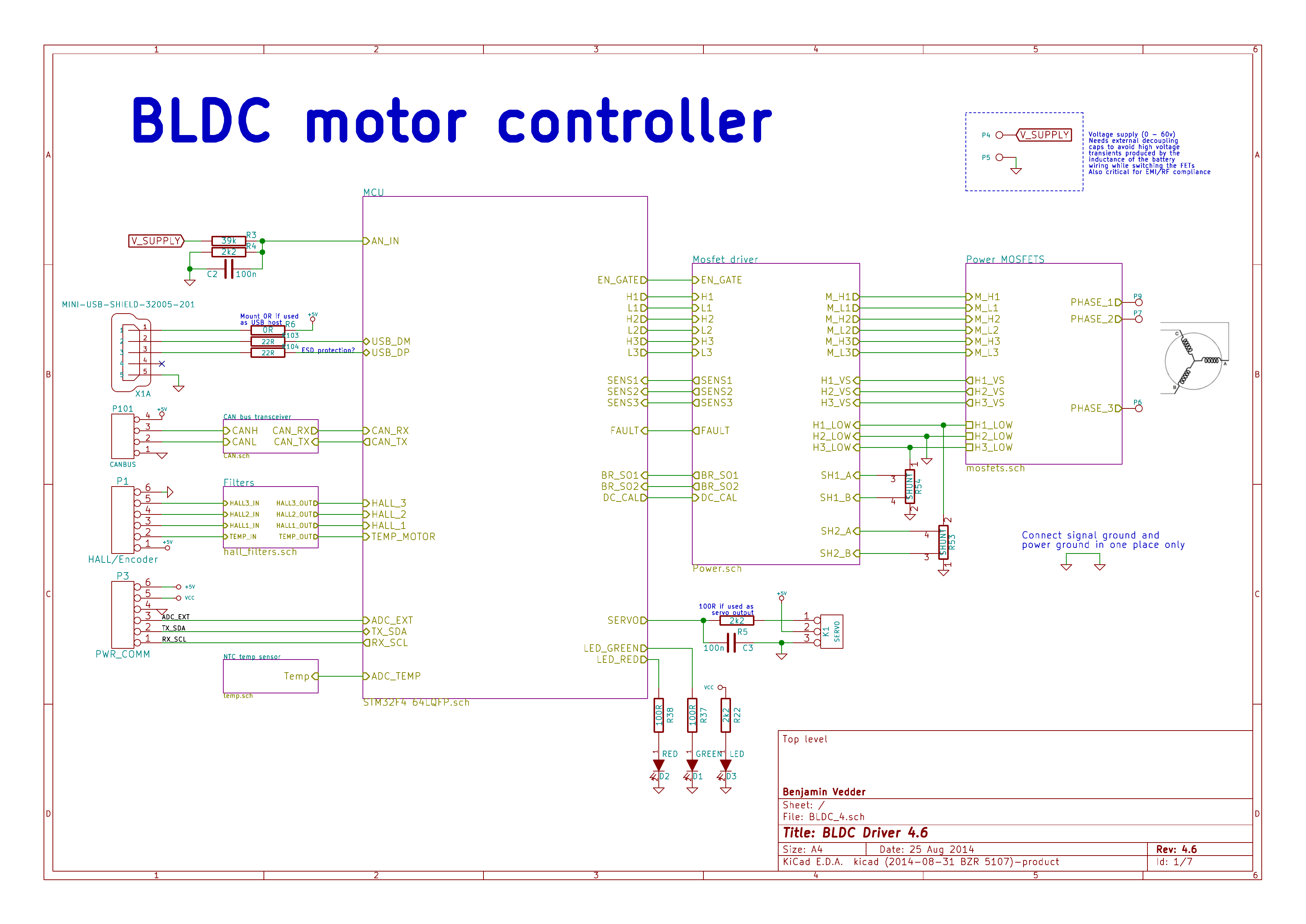
This is an overview of the schematic (download a complete PDF here):
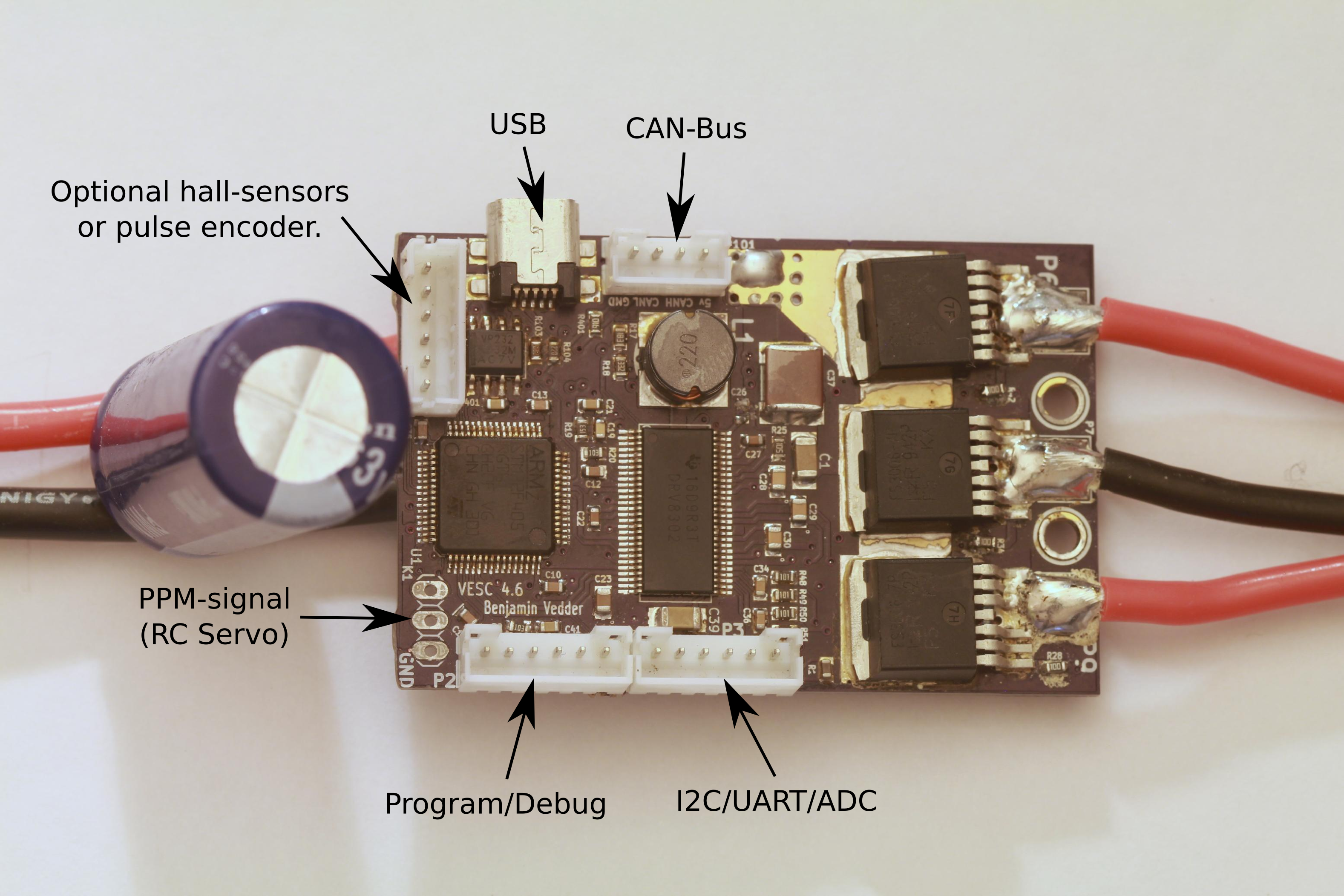
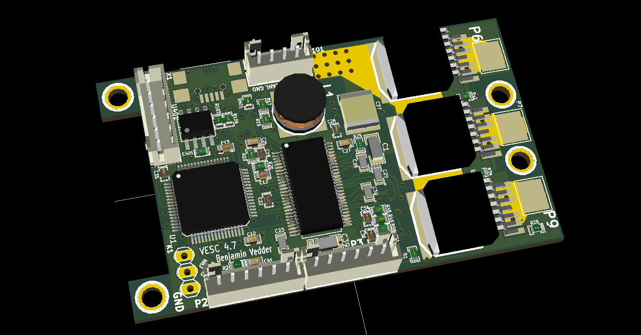
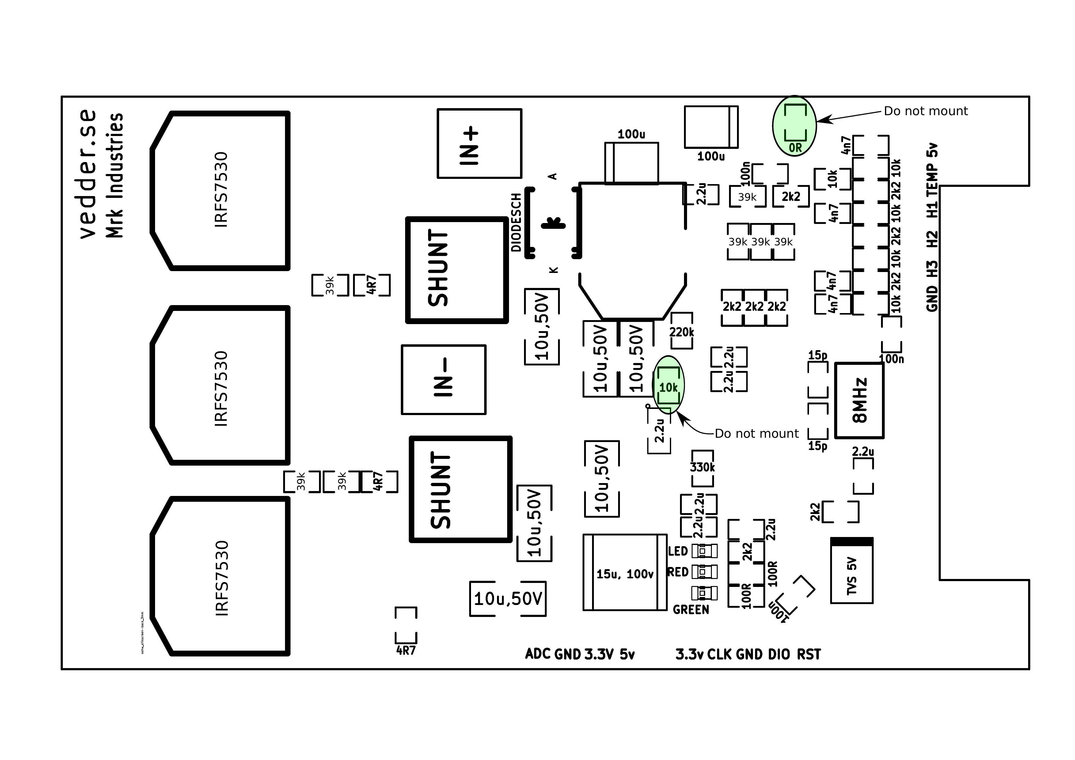
This is the front of the PCB:
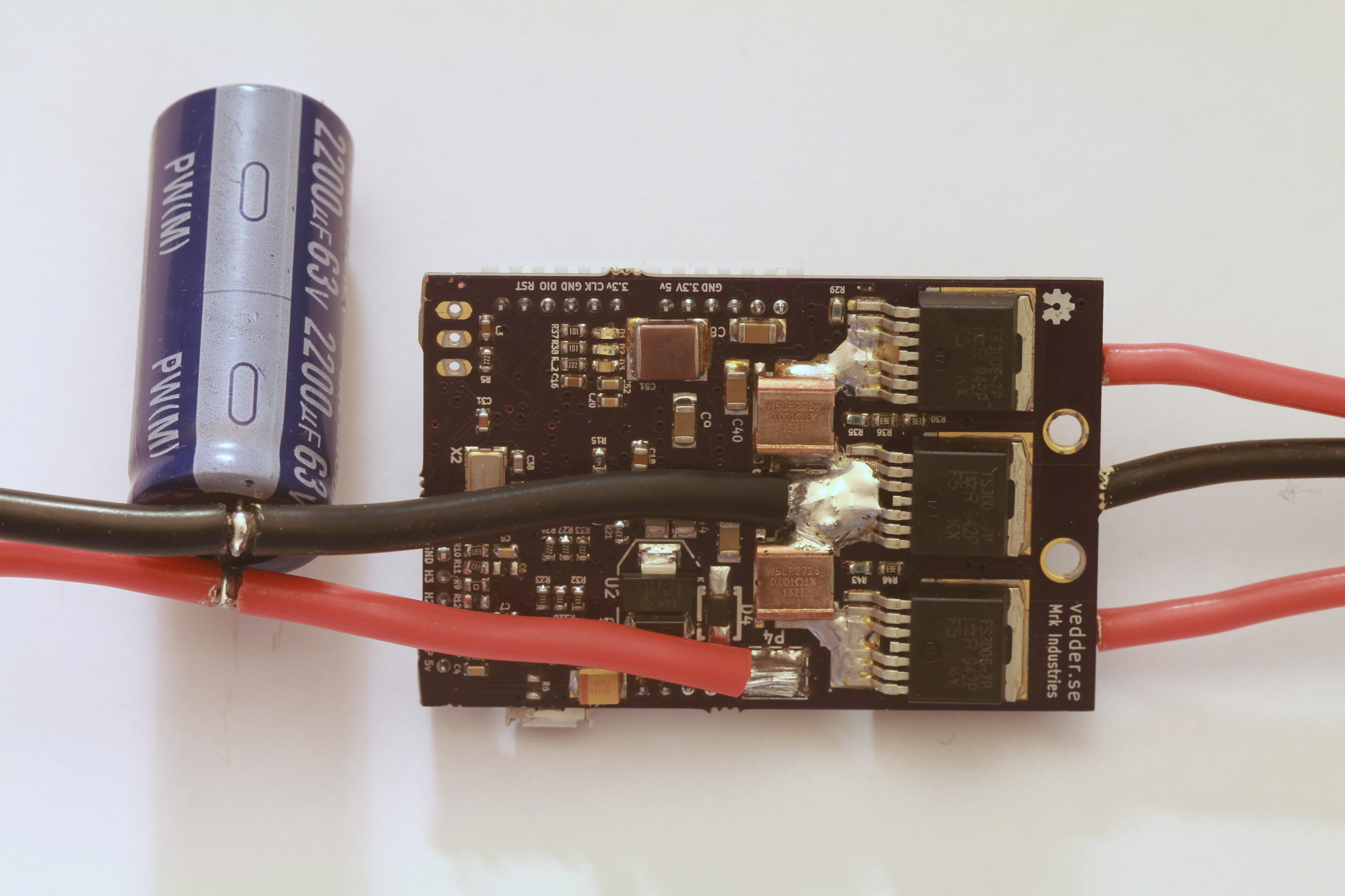
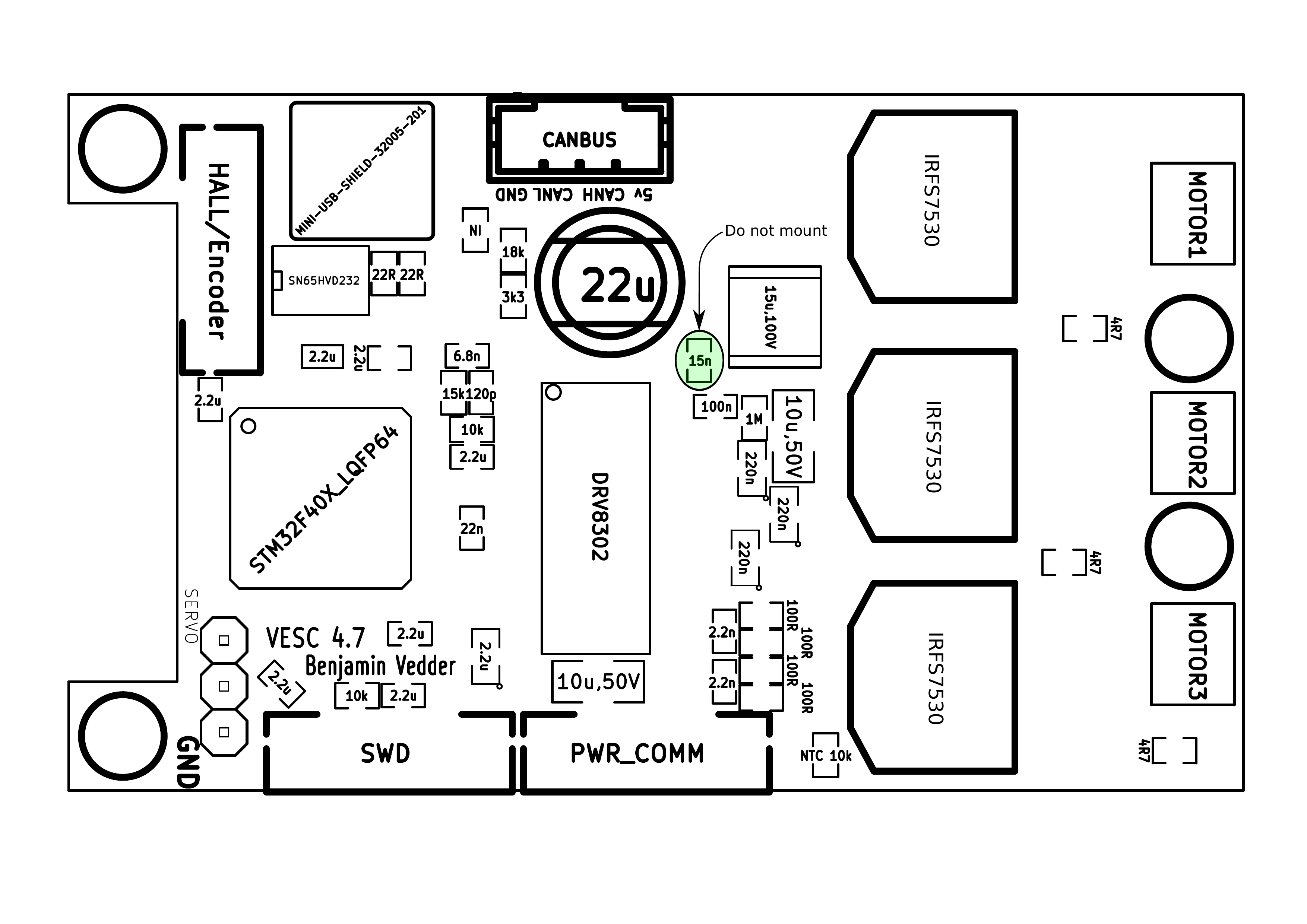
The back:
3D render from KiCad:
Some screenshots of the configuration GUI (BLDC Tool):
Resources
All files are on github to keep them up to date, so check these links on a regular basis:
- Hardware design
- Bill of materials
- Firmware
- Configuration GUI
- Video logger
- osx and windows builds of BLDC Tool, Video logger etc. by Jacob Bloy
Related posts
- Old post motor controller (just for reference)
- Video overlay logging
- Electric skateboard motor tutorial (KV, cells, etc.)
- Startup torque
- Hardware debugging
- Making a programmer
- Writing custom applications
- UART Communication
Forums
Because information about the VESC is scattered all over the internet and a lot of information is in email conversations with me, I have created a forum dedicated to the VESC here.
Live Chat
I have created an IRC channel on freenode where you can live chat with me and other users about VESC and my other projects. Feel free to join: http://webchat.freenode.net/?channels=vedder
Features
- The hardware and software is open source. Since there are plenty of CPU-resources left, the customization possibilities are almost endless.
- STM32F4 microcontroller.
- DRV8302 MOSFET driver / buck converter / current shunt amplifier.
- IRFS7530 MOEFETs (other FETs in the same package also fit).
- 5V 1A output for external electronics from the buck converter integrated on the DRV8302.
- Voltage: 8V – 60V (Safe for 3S to 12S LiPo).
- Current: Up to 240A for a couple of seconds or about 50A continuous depending on the temperature and air circulation around the PCB.
- Sensored and sensorless FOC wich auto-detection of all motor parameters is implemented since FW 2.3.
- Firmware based on ChibiOS/RT.
- PCB size: slightly less than 40mm x 60mm.
- Current and voltage measurement on all phases.
- Regenerative braking.
- DC motors are also supported.
- Sensored or sensorless operation.
- A GUI with lots of configuration parameters
- Adaptive PWM frequency to get as good ADC measurements as possible.
- RPM-based phase advance (or timing/field weakening).
- Good start-up torque in the sensorless mode (and obviously in the sensored mode as well).
- The motor is used as a tachometer, which is good for odometry on modified RC cars.
- Duty-cycle control, speed control or current control.
- Seamless 4-quadrant operation.
- Interface to control the motor: PPM signal (RC servo), analog, UART, I2C, USB or CAN-bus.
- Wireless wii nunchuk (Nyko Kama) control through the I2C port. This is convenient for electric skateboards.
- Consumed and regenerated amp-hour and watt-hour counting.
- Optional PPM signal output. Useful when e.g. controlling an RC car from a raspberry pi or an android device.
- The USB port uses the modem profile, so an Android device can be connected to the motor controller without rooting. Because of the servo output, the odometry and the extra ADC inputs (that can be used for sensors), this is perfect for modifying an RC car to be controlled from Android (or raspberry pi).
- Adjustable protection against
- Low input voltage
- High input voltage
- High motor current
- High input current
- High regenerative braking current (separate limits for the motor and the input)
- Rapid duty cycle changes (ramping)
- High RPM (separate limits for each direction).
- When the current limits are hit, a soft back-off strategy is used while the motor keeps running. If the current becomes way too high, the motor is switched off completely.
- The RPM limit also has a soft back-off strategy.
- Commutation works perfectly even when the speed of the motor changes rapidly. This is due to the fact that the magnetic flux is integrated after the zero crossing instead of adding a delay based on the previous speed.
- When the motor is rotating while the controller is off, the commutations and the direction are tracked. The duty-cycle to get the same speed is also calculated. This is to get a smooth start when the motor is already spinning.
- All of the hardware is ready for sensorless field-oriented control (FOC).
Writing the software is the remaining part. However, I’m not sure if FOC will have many benefits for low inductance high-speed motors besides running a bit quieter.Sensored and sensorless FOC is fully implemented since FW 2.3.
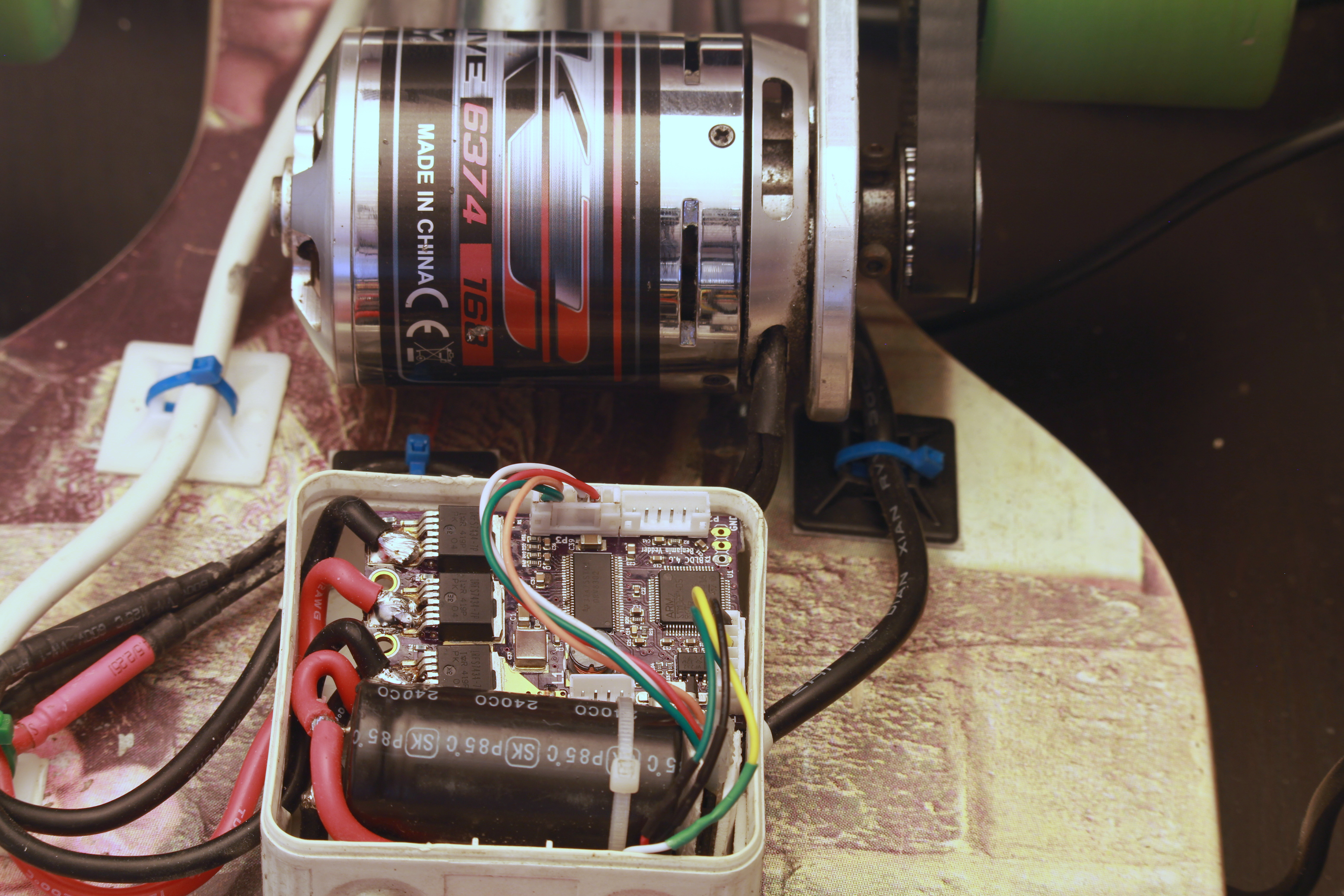
The is the ESC mounted on my electric longboard:
Sensorless startup and low-speed performance:
A short tutorial/demonstration on how to upload the firmware and get your motor running:
My electric longboard:
Video overlay logging (see a post about that here):
Hardware
The PCB is designed using KiCad. Have a look at the links under the Resources heading at the top of this page to find all files. Currently I have no assembled PCBs or kits to sell, but you can order bare PCBs from hackvana with these gerber files. Since hackvana got so many orders for my ESC, Mitch wrote a wiki page about how to order VESC boards from him. That makes it super easy to order the PCBs from him.
The components in the BOM can be ordered from mouser.com. Mouser numbers are included in the BOM as well. Make sure to order a bit extra of small capacitors and resistors in case you drop some of them and since the price doesn’t change much at all. Last I ordered, ordering 10 MOSFETs was cheaper than ordering 6 because there is a price break at 10, so have a look at the price breaks as well.
For assembling the PCBs, the following pictures are useful (the latest versions can be found on github):
Remember to put an electrolytic capacitor close to the ESC on the supply cable. How large it has to be depends on the length and inductance of the battery cables, but I usually use a 2200uF 63V capacitor.
Soldering Tips
This is the best tutorial I have seen so far. It really is as easy as it looks when done right.
- Flux is essential. Without flux, it won’t work. I use a flux pen.
- Lead-free solder is no good. It has more poisonous flux, requires more heat, gives lower quality and is difficult to handle. Don’t use lead-free solder.
- Use a flat, screwdriver-shaped tip. Don’t use a cone tip, because putting solder on the top of it is almost impossible.
- If you get bridges between smd pins, removing them is easy with a soldering wick.
- Make sure to get the alignment right for the microcontroller when soldering the first corner. If you solder multiple corners and the chip is misaligned, you have to use hot air and remove it, then clean the pads and start over.
Here is a video on the technique I use to solder the pad under the DRV8302:
I just put solder on the pad and use a hot air soldering station. Again, using leaded solder makes it easier. When soldering the DRV8302, I first solder the pad using hot air and then I solder the pins with a soldering iron. Notice that the pad under the DRV8302 must be connected for it to work, since it is the ground connection.

VESC Hardware by Benjamin Vedder is licensed under a Creative Commons Attribution-ShareAlike 4.0 International License.
Software Installation and Configuration Tutorial
This a brief tutorial on how to get everything running using a fresh install of Ubuntu 14.04. Here is a video where I do everything live to demonstrate that it isn’t that difficult. Please read all the instructions carefully to avoid most problems.
So let’s open up a terminal and get started…
Preparations
Install a toolchain to compile the firmware (for more details, have a look at this page):
sudo apt-get remove binutils-arm-none- eabi gcc-arm-none-eabi sudo add-apt-repository ppa:terry. guo/gcc- arm-embedded sudo apt-get update sudo apt-get install gcc-arm- none-eabi= 4.9.3.2015q3- 1trusty1
Install other dependencies
sudo apt-get install build-essential qt-sdk openocd git libudev-dev libqt5serialport5-dev
Add yourself to the dialout group to access the USB port of the ESC without being root:
sudo adduser $USER dialout
Uninstall modemmanager (unless you use it) to avoid a delay every time the ESC is plugged in to the USB port:
sudo apt-get remove modemmanager
Add udev rules to access the programmer without being root:
wget vedder.se/Temp/49-stlinkv2.rules
sudo mv 49-stlinkv2.rules /etc/udev/rules.d/
sudo reload udev
Log out and log back in. You should now be ready to compile the firmware, upload the firmware, compile BLDC Tool and run BLDC tool.
Download, Compile and Upload the Firmware
First, connect a programmer as described in this post. Then, download the latest firmware from github, compile and upload it:
mkdir BLDC
cd BLDC
git clone https://github.com/vedderb/bldc.git bldc-firmware
cd bldc-firmware
make upload
cd ..
Note: before running the make upload command, you should open conf_general.h and select which hardware version you are using. It is printed on the PCB. Also, 2015-01-22 I changed the voltage divider resistors to allow up to 60V to be measured by the ADC, so in that case you also have to override VIN_R1 to 39000.0 in conf_general.h.
Download, Compile and Upload the Bootloader
Again, connect a programmer as described in this post. Then, download the latest bootloader from github, compile and upload it:
mkdir BLDC
cd BLDC
git clone https://github.com/vedderb/bldc-bootloader.git bldc-bootloader
cd bldc-bootloader
make upload
cd ..
With the bootloader, BLDC Tool can be used to upgrade the firmware later.
Download, Compile and Start BLDC Tool
From the BLDC directory that you created in the previous step, type:
git clone https://github.com/vedderb/bldc-tool.git bldc-tool
cd bldc-tool
qmake -qt=qt5
make
./BLDC_Tool
You should see the following screen:
Connect the ESC to the USB port of your computer and click “Connect” in BLDC Tool. The lower right corner should now say “Connected”. If you have gotten this far, you should be ready to connect a motor and configure the ESC from BLDC Tool.
Note: If you have more than one usb-modem device in your computer (laptops often have built-in 3g modems), then you have to change ttyACM0 to the port of the ESC. To figure out which ttyACMx port the ESC got, open a terminal and type the following command right after plugging the USB cable in:
dmesg | tail
BLDC Tool can also be started by going to the bldc-tool directory with a file browser and double-clicking on “BLDC_Tool”.
Updating to the Latest Firmware
Updating to the latest firmware and the latest version of BLDC Tool is rather simple. From the bldc-firmware directory, type the following commands while the programming cable is connected to the ESC:
git pull
make upload
Note: Updating the firmware will delete the configuration of the ESC. To save it from BLDC Tool, use the “Read configuration” button and then “Save XML”. After updating the firmware, you can restore it with “Load XML” and “Write configuration”.
Also updating BLDC Tool is important and recommended at the same time as updating the firmware. In order to do that, go to the bldc-tool directory and type:
git pull
qmake
make
Now you have the latest version of the firmware and BLDC Tool. Remember to reconfigure the ESC after these changes.
Motor Configuration
Note: During the configuration, it is assumed that the USB cable is connected to the ESC and that the lower right corner of BLDC Tool says “Connected”.
The first thing to do in the “Motor Configuration” tab is to click “Read configuration” while the ESC is connected to get the current configuration. After that, click “Load XML” and look for a configuration that is the same as or similar to your motor in the “mc_configurations” folder included with BLDC Tool. If you find exactly your motor, you don’t have to change anything unless you want to tweak some parameters for your application.
Note: Even if you load an XML configuration file, use “Read configuration” first anyway because the XML might not contain all parameters. The missing parameters will become blank and can mess with things. Soon I will make sure that sane default parameters are loaded, but I haven’t done that yet.
Sensorless Motor Parameters
Since this ESC uses uncommon techniques to commutate the motor in order to get good low-speed performance without sensors, it is important to set correct motor-dependent parameters in the sensor(less) tab. Otherwise, the motor will run poorly or not at all.
This is what the Sensor(less) configuration page currently looks like (I will probably add more auto-detect options soon):
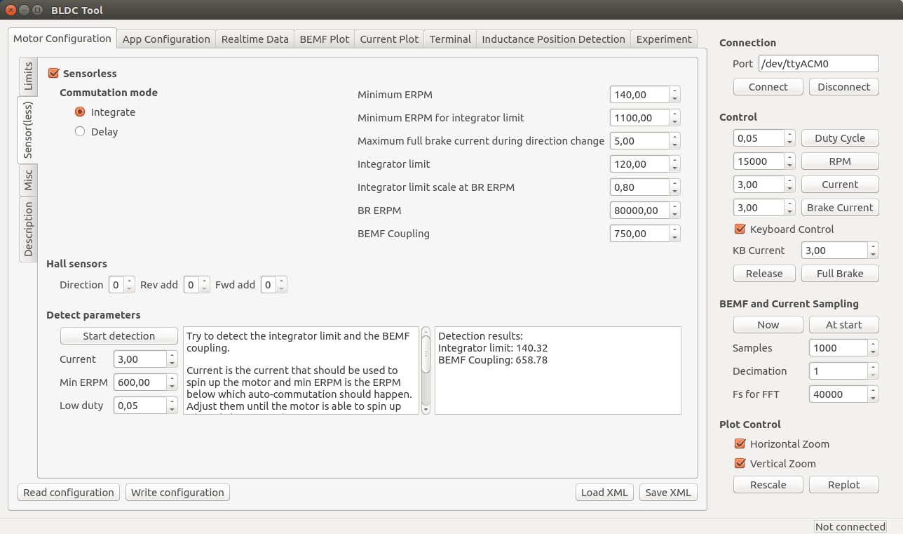
The important motor-dependent parameters are “Integrator limit” and “BEMF Coupling”, and they can be measured with the detection part. I will make a video showing this for several different motors soon, but until then you can try to follow these instructions:
- Connect the motor without any load and make sure that it can spin up freely.
- Make sure that no other input such as PPM is used. If it is, it will stop the motor immediately when the detection tries to start it and the detection will fail.
- Click the “Start detection” button. The motor should spin up, release throttle and then run slowly for a moment.
- If the motor doesn’t spin up properly, Adjust “Current” and “Min ERPM” until it does. In general, small motors should have lower current and higher ERPM and larger motors the other way around. Current usually is in the range 1A to 6A and min ERPM usually is in the range 300 to 1200.
- If spinning up works but running slowly afterwards doesn’t (the motor just stutters), try increasing “Low duty” to 0.1 or so. Increasing low duty will make it easier for the motor to run slowly during the test, but the result will become less accurate.
- Manually put the obtained values into the boxes. I usually round “integrator limit” down to the closest multiple of 5 and “BEMF Coupling” down to the closest multiple of 50. Having them slightly lower than the detection result is good in most cases, so that’s why I round them downwards like that. Getting these parameters perfectly right is not too critical though.
- The next parameters to adjust are “Min ERPM” and “Min ERPM for integrator limit”.
- What they should be depends on the application and is in most cases not too important, but in general lowering them will work better if the load has much inertia. I have Min ERPM around 200 and Min ERPM for integrator limit around 1000 for all my applications.
- You can probably keep the same parameters I have, but if you want to tweak your startup you can experiment with them.
- It is important that “Min ERPM” always is lower than “Max ERPM at full brake” and “Max ERPM at full brake in current control mode” on the “Limits” page.
- Commutation mode should always be “Integrate”.
- The other parameters are for RPM-based timing advance and some other things that aren’t necessary to adjust in the normal case, so I won’t explain them here yet.
For small low-inductance high-speed motors, the delay commutation mode can be used in case the integrate mode does not work. It does not require many parameters, just the minimum RPM which usually can be around 1500. I haven’t tested this mode much, but it is more or less how most hobby ESCs work (which is why it doesn’t require so many motor-specific parameters). Currently it does not support adjustable timing, but I will implement that in a few days since it is quite easy.
Phase advance (other terms: timing adjustment, field weakening)
To compensate for the current lagging behind the voltage at high speeds because of inductance or to get a bit higher top speed at the expense of some efficiency and torque, phase advance can be used. It is implemented in a speed-dependent way so that the motor gets more phase advance the faster it spins. It is implemented this way because having phase advance at low speeds does not give any improvements at all as far as I know, so the best way is to increase the effect as the motor increases its speed. BR ERPM is the electrical RPM of the motor at which the set phase advance is used, and Integrator limit scale at BR ERPM (will rename this option soon…) is the amount of phase advance to use. Setting it to 1.0 gives no phase advance and setting it to 0.0 gives 30 degrees (maximum) phase advance. The set phase advance will be mapped linearly between 0 ERPM and BR ERPM. If you don’t know what this is, you can leave the default options since it is not that important.
Motor
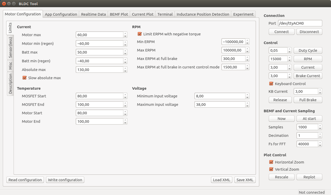
Current, temperature, RPM and voltage-limits can be configured depending on your application.
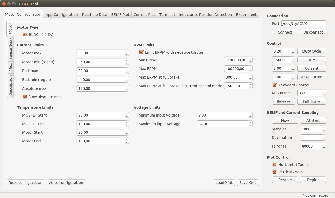
Note: These limits are not foolproof. If you set them too high, you can damage the ESC and/or the motor.
- Current
- Separate limits for acceleration and braking current.
- Separate limits for motor and battery currents.
- “Absolute max” is checked in every PWM switching cycle and used in case the soft back-off strategy for the other limits doesn’t work. I usually set it way higher than the other limits because soft back-off is preferred rather than switching off the motor with a fault code, but it should never be higher than 150A.
- The “Slow absolute max” box will make sure that a filtered version of the maximum current limit is used. This is useful if there is much noise and that fault code kicks in all the time. I usually have it ticked.
- Temperature
- At the “Start” temperature, the current will become more and more limited linearly until the “End” temperature, where the output is switched off completely. Setting them about 20 degrees apart will make the ESC slowly decrease the maximum output current as it gets too warm instead of abruptly switching everything off.
- MOSFET temps (on the ESC) are implemented and working, but motor temps are not implemented yet. They will require an external temperature sensor in the motor. The software implementation is rather simple since I can just copy most of the MOSFET temperature limit code.
- RPM
- Max and Min ERPM are hard RPM limits. It is preferable to use the soft application RPM limits instead if possible.
- “Max ERPM at full brake” (should change the name…) is the highest opposing RPM at which a direction change is allowed. Setting this too high will cause cogging when moving in one direction and giving high throttle in the other direction. On my longboard I have it at 300 and my RC car has it a bit higher.
- “Max ERPM at full brake in CC mode” is the highest RPM at which applying full brake by shorting all the motor windings is allowed. Setting this value too high can cause much mechanical stress in some circumstances. I have it at 1500 for all my applications.
- Voltage
- The minimum and maximum input voltage.
- NOTE: I changed the voltage dividers in hardware 2015-01-22. If you have built the PCB before that, the maximum voltage can’t be more than 52V. The difference is whether the PCB has 33k or 39k resistors. 33k means that maximum 52V can be measured. The latest PCBs (with 39k resistors) can measure 60V, but you should have some margin on your supply voltage to be safe. You can of course replace all 33k resistors with 39k and measure up to 60V.
Once the ESC is configured for your motor, you can use the up and down arrow keys to run the motor forwards or reverse in current control mote, or the right and left arrow keys to run the motor forwards and reverse in duty cycle mode. The buttons in the right-hand side of the GUI can also be used.
Misc
Here are the rest of the motor configuration parameters. You probably want to experiment with Startup boost if you are using current control. The rest of the parameters can be left as their default values unless you have some specific reason to change them.
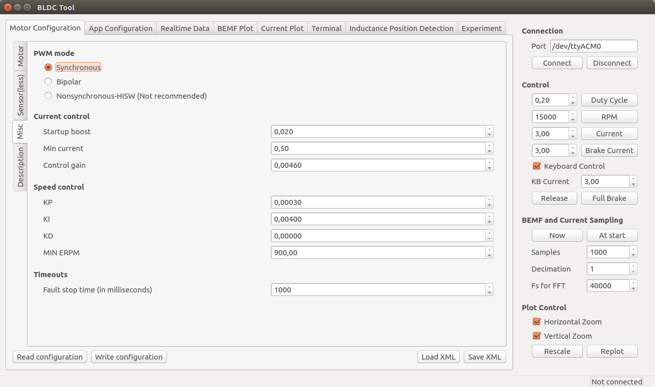
- PWM mode
- Synchronous is recommended and the best choice for a majority of all motors. If you have some weird motor, Bipolar could work better, but it probably won’t. Nonsynchronous is only for experimentation and can kill the ESC if you are unlucky.
- Current control
- Startup boost is the minimum duty cycle to use when using current control. If the motor is to weak when you are just starting, you can increase this parameter a bit until it feels right. The range is 0.0 to 1.0, where 1.0 is full throttle (which you shouldn’t use.). A sane range is up to 0.15 or so.
- Min current is the minimum allowed current. There should be no reason to change this, so leave it at the default value.
- Control gain is the gain used by the current controller. Increasing it makes the current response faster, but also increases the risk of getting an unstable system where the ESC can get damaged. Only change this if you know what you are doing.
- Speed control
- The PID parameters for the speed controller. Only change them if you know what you are doing.
- Timeouts
- Fault stop time is the amount of milliseconds that the ESC should be completely switched of when a fault code arises. After that time, it will switch on and try to listen for commands again.
Application Configuration
First, click “Read configuration” to get the current configuration from the ESC. After that, select which application to use and configure that application.

- Controller ID is the ID of this VESC. If multiple VESCs are connected over CAN-bus, they must have different IDs.
- Send status over CAN has to be enabled to make other VESCs aware of this VESC and some of its current state. It should be enabled for all slave VESCs when connecting multiple VESCs over CAN-bus.
- Changing application requires a reboot. There is a button for that. After a reboot, you have to click connect again.
- Timeout is the amount of milliseconds after which the motor should be shut off in case the control signal is missing.
- “Brake current to use…” can be set to make the motor brake with a certain current when a timeout occurs instead of just releasing it.
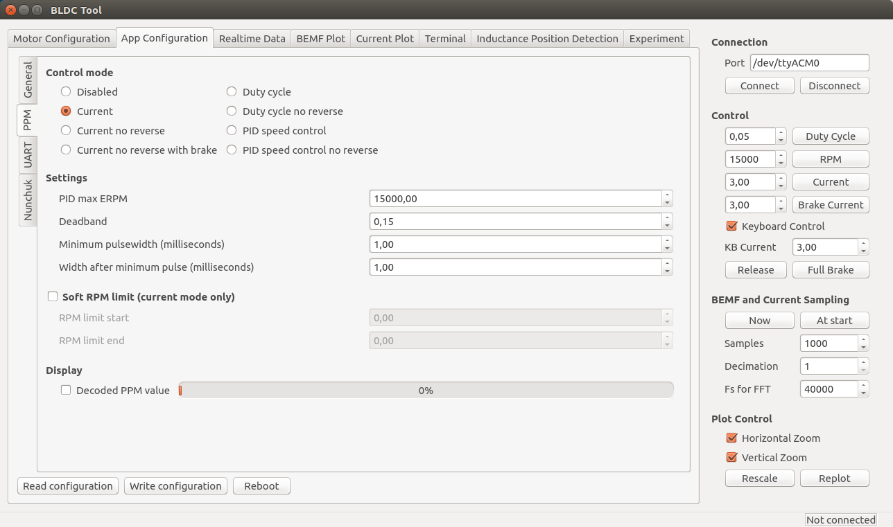
PPM
The signal that a normal RC receiver outputs is a PPM signal, so this can be used when connecting an RC receiver to the servo port.
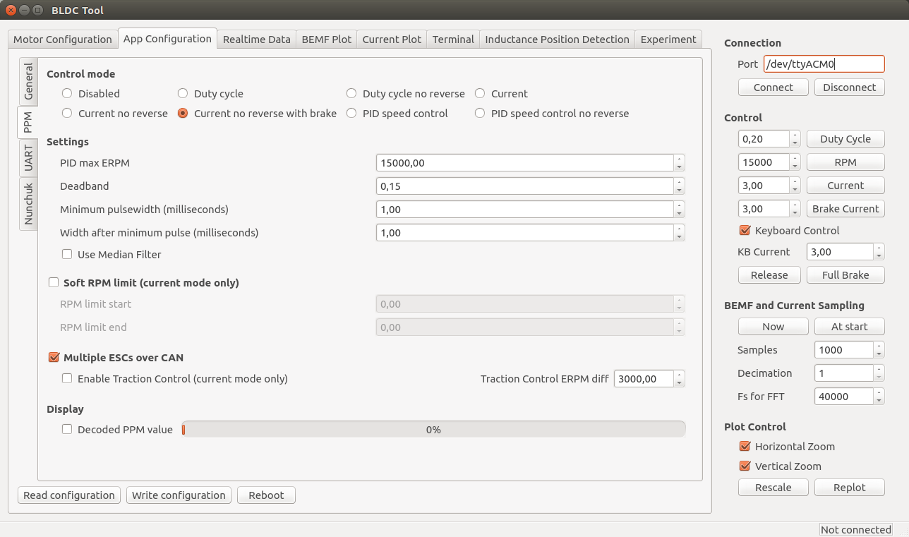
- Control mode
- Disabled: Nothing at all, motor is off.
- Current: Torque control. This is what I prefer since it feels most natural. I haven’t seen hobby ESCs that have current control.
- Current no reverse: Save as above, but no reverse function. Note that centring the now will give half throttle.
- Current no reverse with brake: No reverse, but centre is zero torque. Reversing will brake, but not change motor direction.
- Duty cycle: Duty cycle or voltage control. What most hobby ESCs use.
- PID speed control: The throttle command is intepreted as a speed set command and closed-loop control is used to maintain that speed. “PID max ERPM” sets what max throttle should be interpreted as.
- Settings
- Deadband: how much span in the centre of the throttle should be ignored.
- Minimum and maximum pulsewidth: The timing interpretation of the PPM signal can be adjusted in case your receiver doesn’t follow the specification or it you have some other reason to change it. Setting “Control mode” to “Disabled” and ticking display decoded PPM value is useful when adjusting these.
- Use Median Filter enables a filter that is very useful when there are glitches on the PPM signal. If you have a quadcopter application, you should disable the filter and make sure that there are no glitches since a filter introduces some delay.
- Soft RPM limit.
- Speed limit that can be used in current control mode. Setting the start and end limits a bit apart will result in a soft torque decay when approaching the speed limit.
- Multiple ESCs over CAN can be enabled to connect several VESCs over CAN bus. All VESCs must have different Controller ID and the slave VESCs must have Send status over CAN enabled (see the general tab under app configuration). The slave VESCs don’t need to have any application enabled since they will just be listening for CAN commands. Traction control can also be enabled, which reduces the torque on motors that spin faster than the slowest motor proportional to their speed difference. To connect VESCs over CAN-bus, connect the CANH and CANL signals between them. DO NOT connect 5v and GND because that is likely to cause ground loops which can reset and/or kill the VESCs.
Nunchuk
The Nyko Kama wireless nunchuk can also be used to control the ESC. Note that not all nunchuks for the nintendo wii will work, because they slightly differently.
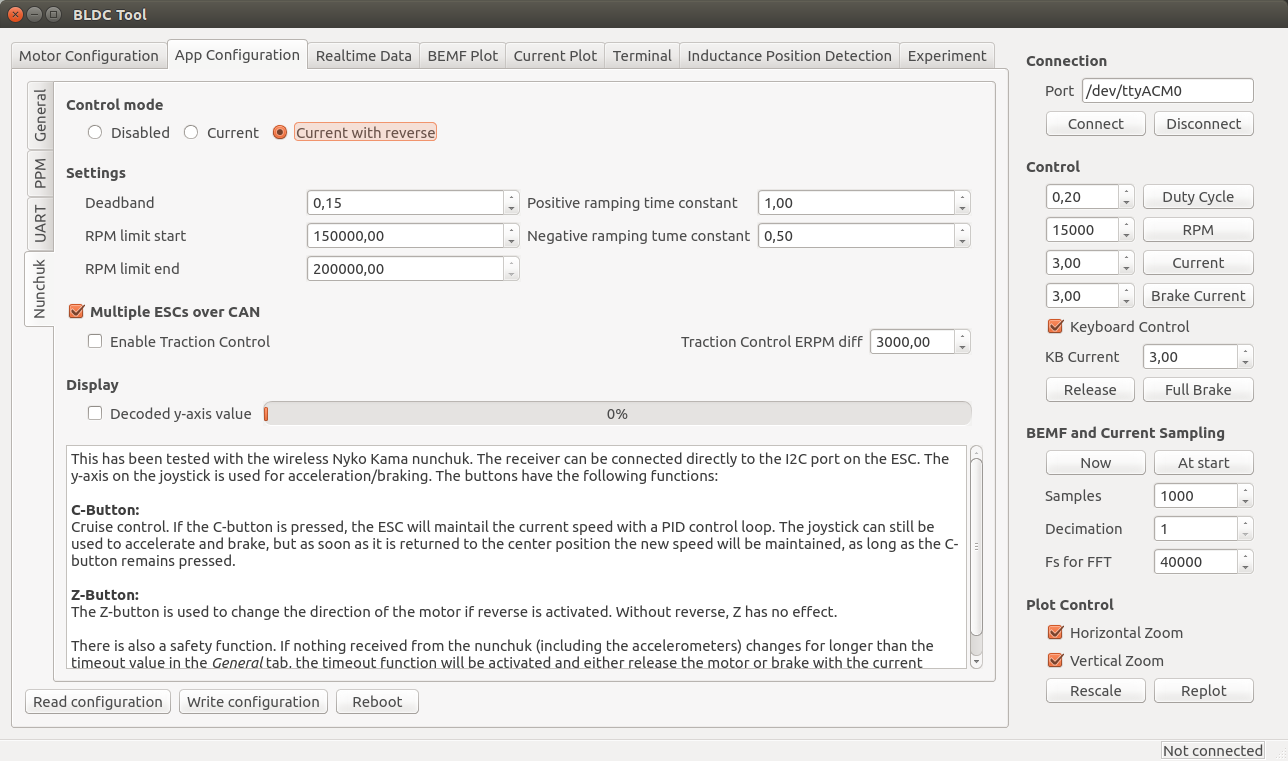
- Control mode
- Disabled or current control with or without reverse. If reverse is used, the Z button is used to toggle a direction change.
- Settings
- Deadband: The span in the centre of the throttle that should be ignored.
- RPM limits: Limit the electrical RPM of the motor. The start value is the point where the torque should start decreasing and the end value is the point where the output will be switched off. Setting them slightly apart will give a soft RPM limit. Setting them very high will disable the RPM limit.
- Ramping time constants: How fast the throttle command should be followed, in seconds.
- Multiple ESCs over CAN can be enabled to connect several VESCs over CAN bus. All VESCs must have different Controller ID and the slave VESCs must have Send status over CAN enabled (see the general tab under app configuration). The slave VESCs don’t need to have any application enabled since they will just be listening for CAN commands. Traction control can also be enabled, which reduces the torque on motors that spin faster than the slowest motor proportional to their speed difference. To connect VESCs over CAN-bus, connect the CANH and CANL signals between them. DO NOT connect 5v and GND because that is likely to cause ground loops which can reset and/or kill the VESCs.
A video where I test this:
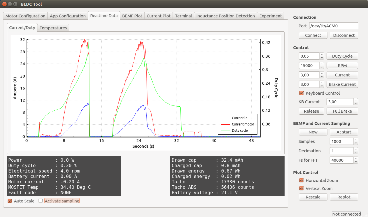
Realtime Data Display
Use the “Realtime Data” tab to display realtime information from the ESC. Make sure that the “Activate sampling” box is checked.
Common Problems and Solutions
As I encounter different problems, I will put them here together with possible solutions for reference.
Uploading the firmware does not work.
- Make sure that you have followed all steps in the tutorial, including adding udev rules to access the programmer without being root.
- Don’t use a too long cable for the SWD connector.
- Make sure that you have a working programmer. I got one from ebay that didn’t work at all and one that died quickly. Otherwise they have been reliable though.
A DRV8302 fault code appears as soon as the motor starts.
- Make sure that R16 is not mounted (see the comment in the schematic).
Connecting to VESC via BLDC Tool does not work.
- Run dmesg to see which ttyACMx port gets assigned to VESC when plugging in the mini-usb cable.
- Make sure that the mini-usb cable is plugged in and that power is connected to VESC. Connecting BLDC Tool is not done via the SWD programmer, but via the mini-usb port.
- If you are using a different usb-connector than the one from the BOM, make sure that the order of the pins is correct. The connector in the BOM is upside-down, so a connector that isn’t will have all the pins mirrored.
My motor is not running properly.
- Make sure that you have configured VESC for your motor as described above. VESC is not plug-and-play and needs an individual configuration for each motor. Without the configuration, the motor will run poorly or not at all. Read the instructions carefully.
Is there a way to “boost” the startup of my motor when using current control?
- Yes, the Startup boost option under Motor Configuration > Misc tab in BLDC Tool can be adjusted as described above.
Update: I have ordered assembled VESCs, some of them are for sale
Update about this update: There are no assembled ESCs left. However, If you are interested in assembled VESCs you can still send me an email as described below so that I can put you on my extra list. If someone changes their mind or if there are other problems, I can send you VESCs that get left.
I have ordered 100 assembled VESCs and they will arrive this or next week. I don’t need all of them, so I will sell some of them for 115€ + shipping. Worldwide shipping with tracking is 20€ per order (which can contain more than one VESC). Shipping within Sweden is less expensive and I will update this post as soon as I know the price. You can contact me by email if you are interested (benjamin at vedder.se). Tell me how many VESCs you’d like and your address, and I will reply with an email that confirms that I have put you in my list. Later, when I have figured out how to accept payments, I will send another email with information about how to do that. As soon as I receive your payment, I will ship the VESC(s) to you and send an email with tracking information
I will update this information in the coming days, so make sure to check if there are updates.

Hi,
I get truble with adding the rules for the programmer.
With
wget vedder.se/Temp/49-stlinkv2.rules
I get
49-stlinkv2.rules Permission denied.
What do I do wrong?
Greatings Andreas
Solved:
sudo wget …
Hello Benjamin,
I am wondering how you have chosen the Decoupeling capacitors and where you have placed them.
The reason is, that you are using quite a lot more capacitors than the datasheets mentions to be nessesary. I guess that some of the capacitors C8 C9 C40 C51 or C1 and C37 are used to decouple the 3 phase inverter Circuit from the rest of the Networks. Where and why are the others used?
I can see that you have placed decoupling close to PVDD(1)(2) which should be enough i guess?
What is your experiences reguarding this?.
Further more you are using a decoupeling cap at the battery right before the PCB which doesnt show on the schematics right?
– Rasmus
I had less capacitors before, but had some issues when using high currents and high voltage. I tried stacking capacitors on that PCB and it was working better. What I have done on this revision is to add as many capacitors as close as I can fit and tried to make the traces as thick and short as possible. One important thing to notice in the design is to connect the power ground and signal ground in only one place.
Yes, there is another capacitor on the input cable close to the PCB that is not shown in the schematic. If the battery is close and the current and voltage is low enough, that one is not needed.
Hello Benjamin,
First, thank you for your awsome work on the VESC :).
I currently building an electrical longboard with
two BLDC motors rated for maximum 65A :
http://alienpowersystem.com/shop/50mm/alien-5065-sensored-outrunner-brushless-motor-220kv-2200w/
I planning to use them at 60A max, because of the hills I have to climb to travel to my job, but on the specification of the VESC you said that it can handle 50A continuous depending on the cooling, so I’ve got some questions :
Which current intensity can I reach with a vesc with a proper cooling system (i.e heat sink and maybe a fan)?
Do you think 60A is possible ?
Which components need to be cooled ?
Do I need an additionnal BMS to manage the battery or the vesc security can do the job?
Sorry if some of my questions are pretty stupid, I’m a software developper,
but I hardly know nothing about electronics.
Thanks a lot in advance for your answers.
Have a good day,
Vincent
Hi Vincent,
I just remembered that you sent me an email with this question, but I forgot about it. Sorry about that.
You can set the current limit to 60A without any problems, even without extra cooling. If the PCB gets too hot, the temperature protection that will decrease the current limit proportional to how warm the PCB is. If you draw 60A for short periods (e.g. during acceleration) the temperature should stay low enough to deliver that. If you draw that much current for longer periods (e.g. a very long and steep hill) the temperature protection will probably kick in and decrease the current. I have this issue with my single motor longboard that has a 3.2kw scorpion motor with 80A current limit without cooling when I go up long and steep hills. However, even without cooling of the PCB, I think the 5065 motors that you linked are the bottleneck when it comes to overheating. Since you are going to use dual motors, you should be fine though. My dual motor longboard with 60A current limit and 6374 motors can take any hill without anything overheating, even without cooling of the VESCs.
Regarding BMS, it depends on what you mean. I don’t use anything additional, but I charge my batteries before they run out completely. There is a low voltage limit hard cutout that you can set, but I will implement something more intelligent soon. For example, when the battery is empty regenerative braking should be allowed but not acceleration.
Thanks a lot Benjamin.
So I will use two VESC :).
And if the hill I have to climb make the thermal protection kick in too
frequently, I will think about a proper cooling system ( i.e thermal paste and heat sink ).
I’ll assume the parts of the VESC that need to be cooled in this case are the 3 IRFS7530, am I right ?
Thanks again for your answers.
Vincent.
I found the middle LED will blink when the DRV8302 regulator output higher than 5V, I built several VESC board, only one board can run which the output is 4.8V, I still don’t know what is the problem.
Hey Vincent,
I am having issues with the BOM link. Could you re-establish the link?
Thanks,
Jacob
Have you considered a dual ESC? It would greately cut cost and weight (very important for my robot). Also could you recommend any replacement transistors for 20A?
Hi,
I’d like to use a 5V cdrom bldc motor to experiment with.. the board already has the driver circuit so I can just control it with my arduino open-loop. My question is, I’d like to tap into the back-emf inorder to do commutation based on zero-crossing, but I’m afraid of connecting it directly to the arduino adc without some protection.
Do you know of any off the shelf pcb or schematic that can be used for this type of thing?
Thanks!
Pingback: VESC – Writing Custom Applications | Benjamin's robotics
Hello Benjamin,
I have asked you about powering the TC2117 in reverse a few months ago, maybe you remember 🙂
I use a discovery board as ST Link V2 programer.
My own board is ready, but programming and debugging by SWD works just when I connect VCC of the discovery (3.0Volts) to the VCC of my board and turn off the DRV.
When I use the own Supply (TC2117= 3v3) the SWD connection fail.
There is of course the difference 3v3 > 3v0.
Do you have the same issue or can you program using the VCC from TC2117?
Best Regards
Hi Benjamin,
Thank you for sharing this amazing project with everyone! I am quite excited to try it out. For those of us that dont know ubuntu, is there any way we can flash it from a windows environment?
Thanks again for uploading this in such detail!
Hi!
I’m just checking in to say how grateful I am because of your open source project. It was fun assembling 2 boards and it feels so good to have them running with such perfection no one had ever seen using hobby escs. Thank you for your work and for creating a perfect ESC.
Regards,
Gal Pavlin
Hello,
I have on problem with my VESC V4.7 with firmware 1.12.
My setup is with an 16inch Brushless DC Hub Motor with 3 Hall Sensors. I used your description in your blog to determine the motor parameters.
In sensorless operation mode the motor performs in both directions similar but I would like to use sensored operation because of the spin up behavior.
In sensored opertion mode the motor spin up very smooth in positive direction (positive rpm setpoint and positive current setpoint) but in negative direction (negative rpm setpoint and negative current setpoint) the motor is very loud and performs very poor.
Currently I use the bldc-tool to control the motor. I plan to use the PPM input with current (torque) control but I need both directions of the motor.
I use the detected sensor table could it be that these table is not perfect?
Is it possible to determine the table by myself?
Is it possible that there is a bug in the software?
Thanks in advance,
Tobias
Hello Benjamin,
I soldered a second VESC 4.7 the sensorless mode works like on VESC #1 but VESC #2 couldn’t detect a HALL sensor table.
I measured the voltage on the sensor interface and the ESC outputs only 3.0V instead of 5V on these pins.
So I did some research where the 5V should come from and found the DRV8302 Buck converter with adjustable output voltage. After some searching on the web I couldn’t find a document which gives me an formula for calculating R17/R18 (on your schematic).
After this I tested the resistors R17 (15,86k ohms), R18 (3,25k ohms), R20 (10,1k ohms) and the connections of the pins 7, 8, 9, 10, 50, 51, 52, 53, 54, 55, 56 (for the connection itself, open pin and short circuit pins) but everything seems fine except of R17 which is a bit out of range but in VESC #1 R17 is only 16,5k ohms and there its no problem with the 5V rail.
Please give me an point where to look for.
Thanks,
Tobias
Sorry for spamming,
found the trick for the 3V – 5V problem. Pulling off some flux and eventually a solder ball did the trick.
But the problem with the poor performance in reverse mode (with HALL sensors active) is still alive (on two equivalent motors and two ESCs)
Regards,
Tobias
Hi Tobias,
The sensored implementation is currently not working with all motors since the sensors might be placed for different timing. I will work on that as soon as I have time.
Hello Benjamin,
i really appreciate your work, it is desiged beautifully!
In my Application I have to power the ESC from a 2S-Lipo. I was wodering if i could disconnect Pin 53&54 from the DRV8302 from V_SUPPLY and provide a high enough Voltage there (e.g. 12V) via a step-up converter from V_LIPO(2S).
I assume that I have to choose one that can provide at least 3A Power for the DRV8302. Any thoughts on that?
Thanks in advance!
Regards, Johannes
I think the DRV8302 could work down to 6V since the DRV8301 can do that, but I haven’t tried that. You can give that a try.
Hi Benjamin,
Thanks for this awesome project firstly. I wanted to use this VESC and built it according to latest schematics on the website ( I guess it is version 4.5 ). Although they are connected just like in the schematics, unfortunately, when I power up the ESC with 21 V, there is something going wrong with TVS diode, its getting hot and a little smoke coming out of it naturally. I have several ESC completed for my project, but all of them has the same problem. TVS diode should be working at 5V but when I measure the voltage on it, I saw 3 V exactly. Do you have any suggestion to find the problem?
Thank you so much in advance.
Tugay
sorry, it is version 4.7
Did you solder the TVS diode in the right direction?
Yes I did. It is exactly like in the schematics.
Hello Tugay,
At one of my ESCs I have the same problem with only 3V instead of 5V (two posts above yours). This problem was caused by a solder ball in the area of R17, R18, R20.
After cleaning these section the voltage was at 5V and the TVS diode were getting very hot and smoking. I solved these problem by resoldering the DRV8302 completely with flux. I think it was a bad solder connection.
After these two fixes the voltage was at 5V and the Diode doesn’t get warm anymore (and is working flawlessly after getting hot and smoking).
Regards,
Tobias
Hello Benjamin.
I am watching this project for several months now. Great work, I must say. And thank you so much for all that work, that you make public.
I myself work in EV industry and can tell there is a large shortage of good motor controllers. By good I mean silent, compact and flexible (configurable, programmable, upgradable, etc.).
So my question is… Would you consider adding FOC? I’m sure it is great now, but FOC would allow a stealth (absolutely silent) operation and less heat (due to space vector modulation, not sure if you are using it already).
Adding FOC has high priority and I’m working on that. The FETs will most likely get warmer since there is more switching even when using SVM, but the motor will run quieter for sure.
Ben,is there anyway you can show how you wired up the Nyko receiver once you took it apart? The only wirless I’ve used allowed the Nyko to be directly plugged into the board. There as no disassembly required……
Hello Benjamin,
really impressed with the work that you have done.
I am interested in wireless connection. How is done, do you have some module? If yes, which one it is?
Regards,
Jan
Hi, how do I use UART commands? Is there any table with commands descrription? Regards
Not yet, but I hope I will have time to write a post about that soon.
Is it possible to access diffs or old version for the BOM? I had some of the v4.7 PCBs printed at OSH Park, and I’m about to buy the components, but now the git repo has the 4.8 BOM. They don’t look hugely different, but I have, for example, some LM73CIMK temp sensors in my mouser basket, and I can’t work out if they’re totally unrelated, or if they were on the V4.7 BOM. There are some notes on the BOM about “after 4.6”, etc, but it would be great to get the canonical v4.7 BOM.
You can download the 4.7 BOM here:
https://github.com/vedderb/bldc-hardware/raw/3e84ddbce5fd3794db2d54da402499e07997cc40/design/BLDC4.7_BOM.ods
on github you can see earlier versions of the repository from the commit log.
hi,
can i use an external microcontroller like arduino to send command to the vesc?
Yes, you can. I will write a tutorial about that when I have time.
Pingback: Open Source ESC Developed for Longboard Commute | Hackaday
Pingback: Open Source ESC Developed for Longboard Commute | Ad Pub
You appear not to be using any schottky diodes, are those a thing of the past with the newer MOSFETS? I’m also impressed with the specs for those mosfets, how did you come across them?
Hello Benjamin, i will use your ESC but i need 150A continuous, you can suggest something?
Best Regards
Nicola
Hi,
you would need to redesign the power stage on the PCB to add a lot of cooling and change the shunts, but it could work.
Hi, to increase current capability of output stage u simply need to have mosfets in a parallel topology. twice mosfet twice current, triple mosfet in parallel triple current..
Regards
It is not that easy since the DRV8302 cannot supply enough power do drive more gate capacitance at high switching frequency. These FETs are the limit of what it can handle.
Hello,
have you tested the minimum supply voltage of 8Volts? I think your Fets need at least 10v @ Vgs.
Hi,
The drv8302 has a charge pump for handling that, so it should work.
Hi,
I hope this project is not dead as ur last update was several month ago. I use 1/8 scale Buggy and here in germany several people are interested in this project. There are several really nice feature. I aksed myself if its possible to raise the continous current this ESC can handle. We use 4S LiPo in the buggy. Most commericial ESC can handle about 120A continous and up to 250A burst. I made a vid with a monster truck but unfortunatly on a low grip surface. Can the ESC handle the car on grass/ astroturf and similar surfaces?
Hi,
I haven’t updated this post for a while, but I’m working on the project almost every day after work. The latest github commits are from yesterday. 4s is not an optimal voltage for the VESC since you need high current to get high output power. So you should choose the lowest possible motor kv and highest possible battery voltage to make it work better.
I actually have a 1:8 buggy that I’m testing the VESC on. Right now I’m borrowing a castle 1717 motor and run on 6s. Here is a video of some tests I made recently:
https://www.youtube.com/watch?v=cnkrGPJvTj4
The gearing is for 150 km/h and the current limit in this test is 120A and the temperature limit is never reached. RC cars usually don’t run at full current for very long since there is nowhere to put that much energy after the initial acceleration.
Unfortunatly the rules say 4S hardcase LiPo..i know that a high voltage setup is smarter to get the power down. As longer i read threads about your ESC the more i see i will get probs with the daily handling of it..looks like i had to install linux on a netbook u really use the options properly…
Hi, to increase current capability of output stage u simply need to have mosfets in a parallel topology. twice mosfet twice current, triple mosfet in parallel triple current..
Peace
For higher current I think the easiest is to replace the current IRFS7530 MOSFETs with even better, but more expensive transistors with same or less gatecharge and switching performance. One candidate (with a really cool number) is IPT007 which handles 300A and has only 0.75 mohm Rdson and also less gatecharge. With IPT007 and tuning of current sense it should allow around 100A continously. But It might require recalculating gatedriver settings due to different transistor characteristics.
But as Benjamin wrote, the best way to get more performance is to increase voltage if possible.
Hi Benjamin, I have some units of HW4.7 PCB. I saw new version HW4.10 is available, but it’s 4layer’s wich makes PCB more expensive..
Could you tell me if HW4.8 is still 2layer PCB and where can I get gerber files for latest HW using only 2layer PCB?
I really like this controller, its advanced and features regenerative charging.
I’m doing some experiments focused on regenerative feature, and have question about how can I have a output control pin to enable some external circuit during regenerative time? A kind of control output which is low during normal power supplying to motor and high level while backEMF from motor detected.
The ideia behind is to redirect reversed current through a external circuit for optimizing regenerative energy drawn to battery, but this circuit must be only enabled when backEMF from motor detected using this control signal.
Any discussion or ideias about this are welcome
Best regards,Vitor
Hi Vitor,
all versions are 4 layers and they have been that from the beginning. There is no way I could fit everything in two layers and make it this compact.
You could write an application that sets a pin when regenerative braking is used, it is quite easy. You can also use the uart, usb or can interface and read when the current becomes negative, but I haven’t documented that yet. You can look at the code in bldc tool though.
Hi, confusion about layers.. anyway I do some reserch on energy harvesting and saw that conventional regenarative methods on EV’s are only abble to absorb some portion of energy during brake.
BackEMF happen when potential voltage on motor side is higher that battery voltage, making current flowing in battery direction. But imagin an example of a motor powered by 12 lipo ( 12 * ~4V = 48V) batteries. Battery will only receive charge if motor generate > 48V making all voltages under 48V unusable.. If motor is for example generating 30V will not be enough to put charge into battery.
If all voltage spectrum of motor could be reused , an more efficient system we have, maybe twice or triple energy could be regenerated.
So to support this ideia circuit could have mosfet swithing rails which will turn on/off external circuit and redirect current if voltage generated by motor is <48V to an step-up boost topology circuit which will boost most voltage spectrum generated under 48V and draw back to battery. This energy spectrum under 48V is all wasted when not boosted up.
Hope I was clear about this concept
E
Regards,
Vitor
When the motor generates lower back emf than the battery voltage it can be used for regenerative braking with high efficiency anyway. When using synchronous switching with a duty cycle that corresponds to lower voltage than the back emf voltage the motor inductance will essentially be used as a boost converter, which means that the motor acts as a generator and a switched mode power supply at the same time. This is implemented in the code and works well.
Hey Benjamin,
Do you think this could be used to control servo motors ? (BLDC + rotary encoder)
This could help making really cheap alternatives to stepper motors for some DIY CNC projects.
Thanks,
Fabien.
Hi,
Do you do any custom versions of this? I am looking for a ESC which can provide excellent linear control of R/C brushless motors from 0 – 10,000 rpms with +/- 10 rpm resolution using a optical sensor to detect motor rpm and provide speed feedback.
The VESC can already do that. You need to find out/calculate the electrical rpm of your motor at 10.000 rpm, put this number in “PID max ERPM” and use a controling way that suits your need of accuracy.
Hi Benjamin, could you give me reference for the two diodes and for the 8Mhz ocillator?
Regards
And you don’t need an optical sensor, as the controller knows the exact ERPM (which is linear to the real RPM).
Hi, I’m trying to upload bldc-firmware and I keep failing.
My error code is
WARNING: target/stm32f4x_stlink.cfg is deprecated, please switch to target/stm32f4x.cfg
Info : auto-selecting first available session transport “hla_swd”. To override use ‘transport select ‘.
Info : The selected transport took over low-level target control. The results might differ compared to plain JTAG/SWD
adapter speed: 2000 kHz
adapter_nsrst_delay: 100
none separate
Info : Unable to match requested speed 2000 kHz, using 1800 kHz
Info : Unable to match requested speed 2000 kHz, using 1800 kHz
Info : clock speed 1800 kHz
Info : STLINK v2 JTAG v23 API v2 SWIM v4 VID 0x0483 PID 0x3748
Info : using stlink api v2
Info : Target voltage: 1.566798
Error: init mode failed (unable to connect to the target)
in procedure ‘program’
in procedure ‘init’ called at file “embedded:startup.tcl”, line 473
in procedure ‘ocd_bouncer’
** OpenOCD init failed **
shutdown command invoked
make: *** [upload] Error 1
I use ST-LINK/V2 programmer and I looked up for the datasheet(http://www.st.com/st-web-ui/static/active/en/resource/technical/document/user_manual/DM00026748.pdf) to connect stlink to vesc. I used
PIN 3 – TRST – RST
PIN 9 – TCK_SWCLK – CLK
PIN 7 – TMS_SWDIO – DIO
PIN 19 – VDD(3.3V) – 3V3
other GND pins to GND
Please help
Thanks
hello thanx for the great information
can i use this controller with my e-bike BLDC motor 48v 1000Wh ?
Hej!
Har du nån esc kvar monterad? även intresserad om du bara har kort omonterade…
Med vänlig hälsning jimmy
Pingback: My Electric Longboard Build – BOM | Anthony Ngu
Just wanted to thank you for your great work. I just finished soldering 2 ESCs and they are doing very good! (Sadly my motor is not very powerful)
https://www.youtube.com/watch?v=YnCMogjBV8o
Ole. 🙂
Nice 🙂
Did the detection work? Are you running sensorless? I had to tweak the parameters a bit for making it work on my ebike, and I haven’t really documented what I tweaked yet.
The detection worked, – since the motor is geared it can spin freely in reverse direction. I wired it to run backwards for the detection. Worked fine. The motor actually has sensors, but I don’t use them. The startup torque is a litte weak, but still good. I will play with the parameters, and was thinking about putting a NTC inside the wheel hub – then try to max out the motor.
Right now, I am looking for a logging solution. Since I don’t want to carry my notebook – I’m trying to setup a python board with a sd card. Also driving a display with real-time stats would be nice to have. Do you have already a solution for this?
Ole.
Just wondering if one day you could add provision for an external ON-OFF switch between V_supply (battery high voltage) and DRV8032 + STM analog input. Leaving only the hi side FET drains connected permanently to the battery, with little current leakage. Anti spark would be avoided I guess (provided everything goes fine upon startup in these conditions)
Hi! What would be best place (and price) to order VESC from? I am from Baltic states (Latvia).
I can solder it myself if it is possible to order PCB and parts only.
Seems like this is the best option for electric skateboard.
Thanks!
Vedder, i built a version 4.10. I was able to flash the firmware without issue but I am not able to get any motor detection, it keeps failing. I checked the fault code and it is FAULT_CODE_OVER_TEMP_FET.
Real time data shows the temp on all parameters fluctuating around 400 degrees. Any ideas?
The ADC pins are moved around, so you have to change hardware version to 4.10 in conf_general.h. Also, I haven’t tested 4.10 myself yet, so I don’t know if my hardware configuration is correct yet.
Got it sorted, thank you! Any idea when the bldc tool will be updated with the FOC control?
Everything in the video I uploaded is implemented and running, but I want to polish the implementation a bit more. I could push everything to github as it is now, but I don’t know how useful it will be for most users yet.
I am considering using this ESC in an application where it is driving a fairly large motor that is rated for 90A continuous. While I expect the average draw to be more like 40A I am still going to consider adding extra heat sinking. Anyways, what worries me is that in my application the motor may stall. The internal resistance is .014 ohms and the voltage is 42 volts.
What would happen? Would the controller attempt to continue to produce torque at the software defined current limit? or would such a draw be so large that it would trigger the ESC to shut off the output.
The current limit is still applied when the motor stalls, so there shouldn’t be a problem
In version 4.10 (and earlier I think) the BEMF sensor signals are not labeled the same on the inputs and outputs. On P.7 of the schematic with the BEMF resistor dividers, the H3_VS is connected to SENS1 and similarly H1_VS is connected to SENS3
Obviously this doesn’t matter to sensorless motors but for Hall sensored motors I think there might be problems… Yes, no?
This is mapped in software. You can configure the hall sensor table to work will all combinations of how the motor cables and sensor cables are connected.
I’ve wanted a high quality motor controller for some time, so thank you for your efforts on the project. I’m hoping to control a small centrifugal vapor pump for a hobby project that has stalled in part due to lack of an affordable quality motor controller – the RC ESC’s did not work for me. Have you tested the controller with any high RPM 70K+ motors (2 pole of course)? Any suggestions on high RPM continuous use motors that are known to work well with VESC? I looked at the Maxon EC19 120 W motors, but they are $300 and was hoping to find something cheaper. I’m looking for a motor with ~75 to 250 watts of power. Thanks!
With two poles you should be able to go up to around 90K RPM. I don’t know which motors to use for continuous use though, most hobby motors will probably fail quite early. Maxon motors have good quality, but they are expensive as you mentioned.
Pingback: RCbenchmark Dynamometer motor tester - R/C Tech Forums
Hello Benjamin,
iam testing your ESC and your Firmware. But the detection doesn’t work. “Detection failed. Bad detection”
I have tested 2 motors. The first is a Graupner Outrunner with around 1200kv and the other one is a Tenshock Inrunner with 2500kv.
And in Delay mode the motors run very bad.
I hope you can give me some tips.
HW 4.7
FW 1.10
Battery 4S Lipo
You probably have to adjust the detection parameters for those.
I am curious how this ESC design could be scaled-up….do you have an idea for limits on continuous current and voltage?
I know bullets are typically used between the motor and the VESC, but would there be any reason to not use Anderson power poles? The 45A rated connectors should be fine for my motor. I know power poles are often used between the battery and ESC and there are different color housings besides red/black. I was concerned noise might be an issue though, and didn’t want to damage the VESC. Thanks
Anderson power poles are spec’d for DC and I discovered with the AC on the brushless motor phases that there can be issues with noise that might also make the ESC unhappy. I don’t have a VESC to test with yet but it did seem to be an issue with the hobbyking varieties.
Hello !! incredible circuit !!!
Small question , can it handle a quadrature encoder for feedback ?
Cheers !!
Thanks! Yes, that is possible and implemented. It will be more integrated with the FOC implementation when I release it.
Hi,Benjamin, thanks for your project to make me sense in BLDC&ESC.
I am wondering to raise power voltage to 75v for my high duty quadrotor, and you have mentioned that to redesign driver, FETs and some code, but I couldn’t find out any driver chips higher than DVR8302 in same package. Can you please give me some specific suggestions? That I can try with no stress.
Thans a lot. Hope FOC coming soon,
Adam
Hi Adam,
A while ago I used drivers named FAN7390. They can only drive one half bridge, but can go up to 600V. If you use them you have to add amplifiers for the currents, a buck converter for power and some regulator for 12V for driving the gates.
I have been working on FOC a lot recently and most things are finished. I have also implemented detection functions for motor resistance, inductance and flux linkage to make the sensorless implementation usable without knowing the motor parameters before. Hopefully I can do some more testing in the next days and push it to github then.
/Benjamin
Hi Benjamin,
Thank you very much for your hit, I found so many gate drivers like FAN7390, just in different brand. But I’m not sure that you said ‘add amplifiers for the currents’, are you mean this is the Current Sense offset to STM32?
Does a buck converter works for the logic power of the board?
For the FAN7390’s VDD, apply a regulator for 12V for driving Mosfet gate? is that right?
Sorry for my ignorance, Thank you again.
Adam