One of the major challenges when working on my custom open source ESC was to get good startup torque and low-speed performance with sensorless motors. This challenge has been addressed in several places around the net:
- Here is one article where Team Novak explain why sensored systems are superior to sensorless systems: http://teamnovak.com/tech_info/view_article/24
- This article about electric scooters has some information about that topic too: http://www.instructables.com/id/The-New-and-Improved-Brushless-Electric-Scooter-Po/step4/Controlling-the-Outrunner-Sensorless-or-Sensored/
- The metroboard has modified motors with hall sensors: http://metro-board.com/brushless-outrunner-motor-testing/
- The marbel electric skateboard also uses hall sensors: http://howtomakeanelectricskateboard.wordpress.com/2014/06/22/marbel-kickstarter/
- Here is a video of an electric longboard with a standard sensorless hobby ESC. There are obvious startup and low-speed issues: http://www.youtube.com/watch?v=SNt70MdUh0Q
Techniques I used
In order to get a smooth and quick startup without sensors I used several tricks, namely:
- There are no hardware low-pass filters that introduce phase delay. Such filters can be avoided because the ADC samples are synchronized to the PWM timer and adjusted dynamically every time the duty cycle or switching frequency is changed.
- After a zero crossing, the area under the voltage is integrated until a threshold for commutation based on the motor parameters. This integration is robust agaist acceleration and provides good SNR since an integrator is a low-pass filter.
- There is a parameter that defines the voltage coupling between the windings when measuring the back-emf. This make a huge difference when running at low speeds with low duty cycle. This compensation has a RPM dependence though, which is something I tried to avoid where possible because the RPM estimation has a delay and thus causes problems during acceleration.
- To get better voltage samples, the switching frequency is adaptive and proportional to the duty cycle. This is because the back-EMF only can be sampled during the ON-time of the PWM cycle and low duty cycles have short ON time. Since the motor is running slowly on low duty cycles, sampling and switching does not have to be as fast to keep up with the motor which makes this less of a problem. Lower switching frequency also decreases switching losses, which is a positive side-effect.
- When the motor is un-driven, the back-emf on all phases is analysed to track the position, direction and speed of the motor. So when the motor is already spinning, the algorithm will begin in the exact state of the motor (position, duty-cycle, direction).
- I have also used some hack-ish conditions based on trial and error to improve the startup.
- Closed loop operation is used from the first commutation, since the measured values are clean enough when using these techniques.
This is a video where I demonstrate how this works on a scorpion outrunner and an electric longboard:
Some examples with plots
** Note that all the plots show the voltages samples captured by the motor controller, which are synchronized to the PWM timer. It would look different on an oscilloscope since the switching distorts the signal. **
This is what the phase voltage for a typical startup sequence looks like, where the duty cycle is set to 5%:
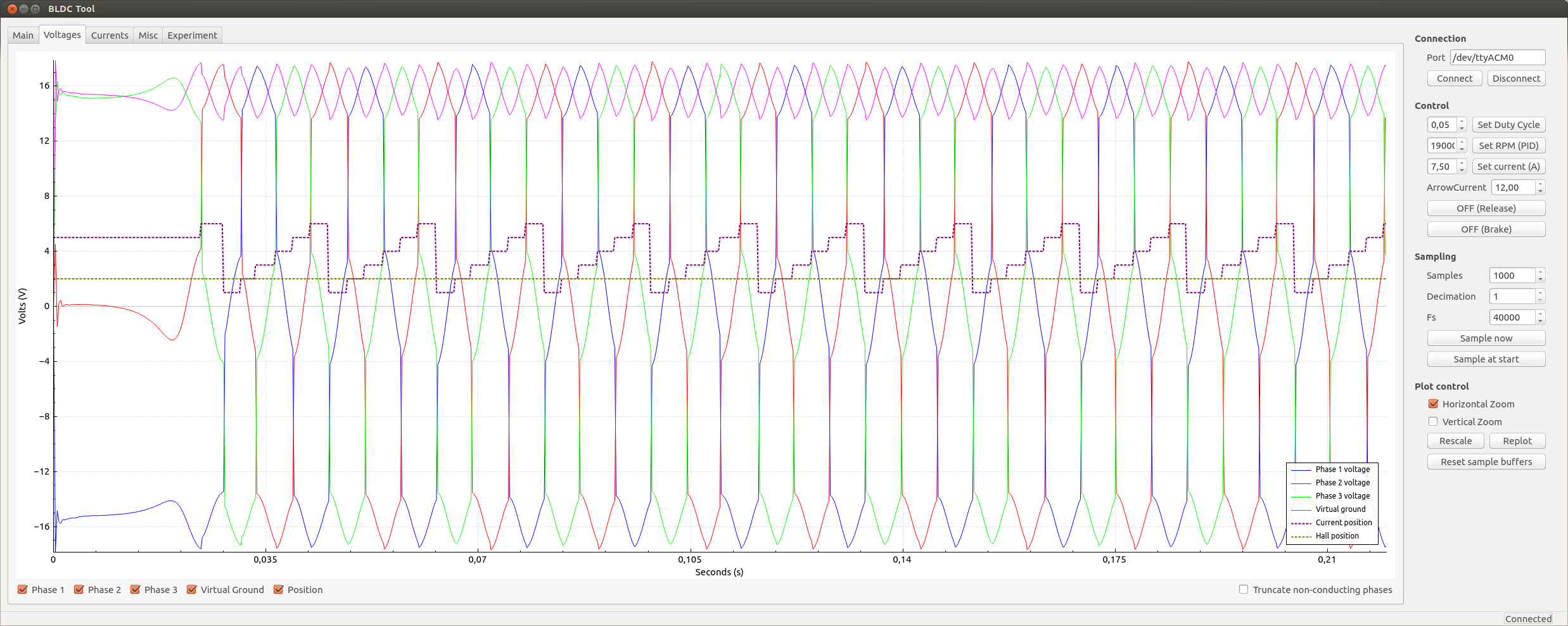
Even though the duty cycle is only 5%, the waveform is clean. This is because the switching frequency is low at this speed and the on-time is long enough to get good samples. The first commutation is a bit off at first since the motor is not perfectly aligned, but the second commutation already looks perfect.
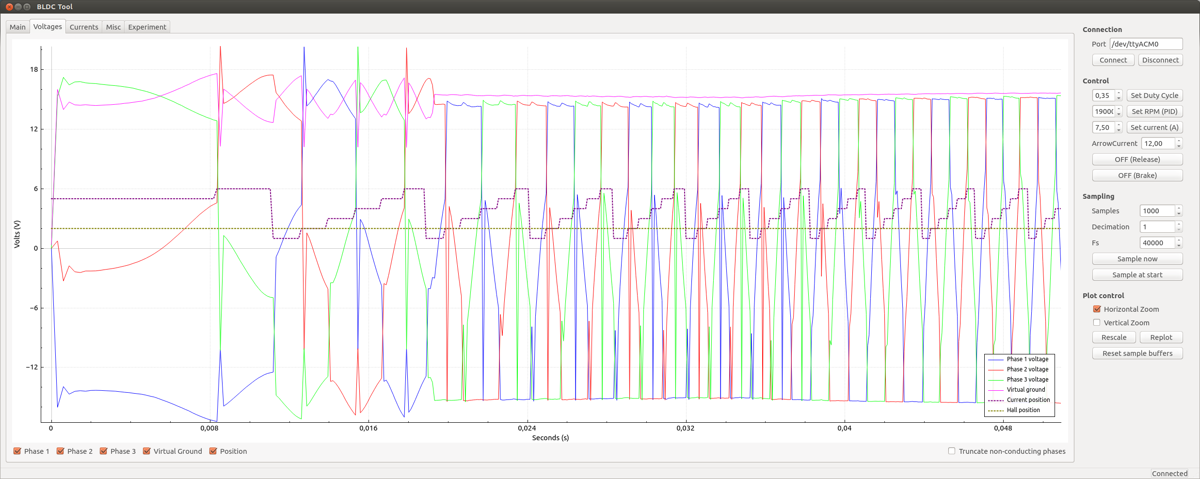
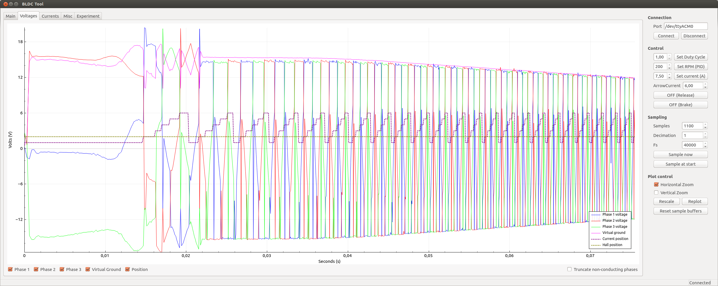
Here is another example with 35% duty cycle:
And this is the measured current for the same startup:
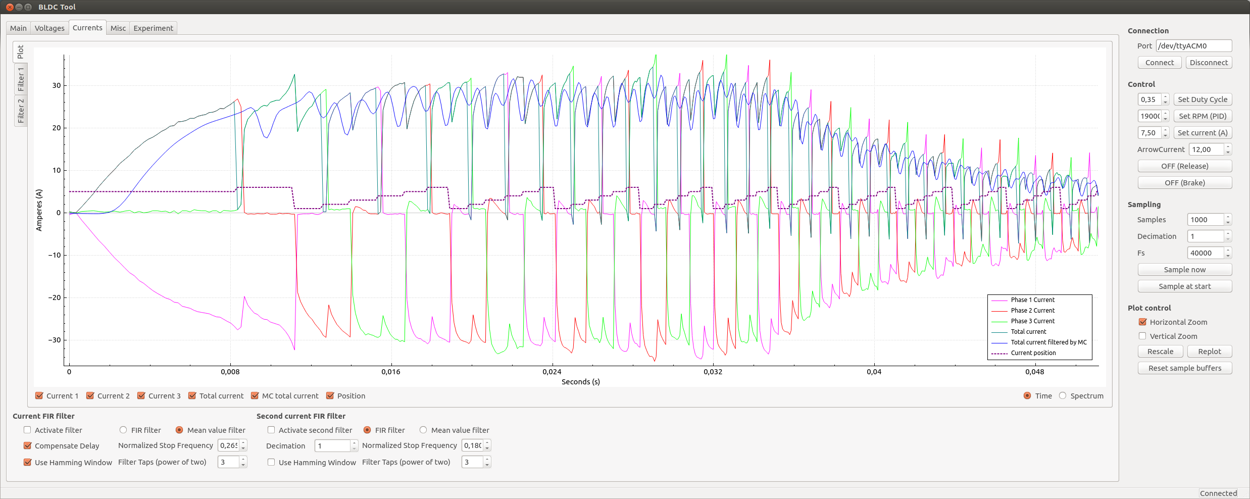
Here the phase voltage has some commutation spikes in the beginning because the current is quite high during acceleration, but even so the commutations are even and clean.
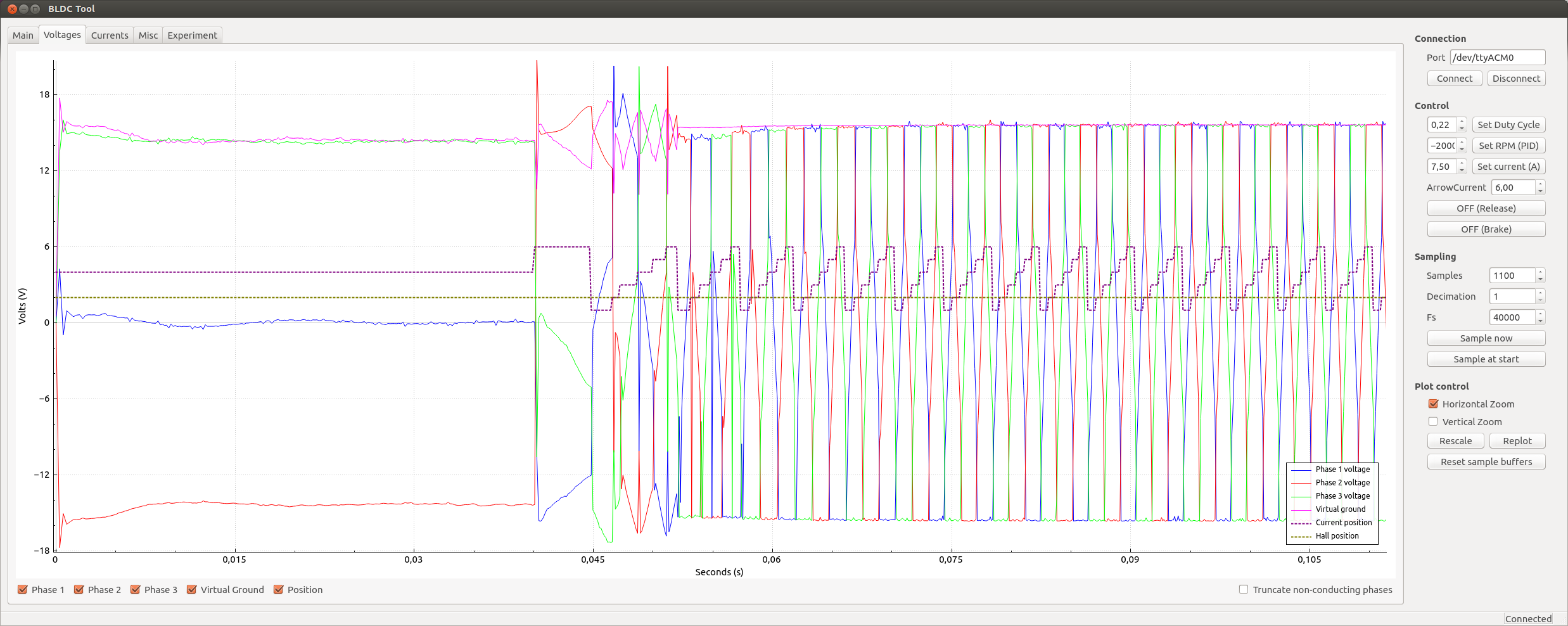
Here is an example where the duty cycle is ramped towards 100% rapidly:
Again, because of the current, there are commutation spikes on the voltage. The voltage from my lab power supply is also dropping because of the load. Even so, the commutations are even and clean.
Here is one unusual case, for which I had to restart the motor 20 or 30 times to get it captured:
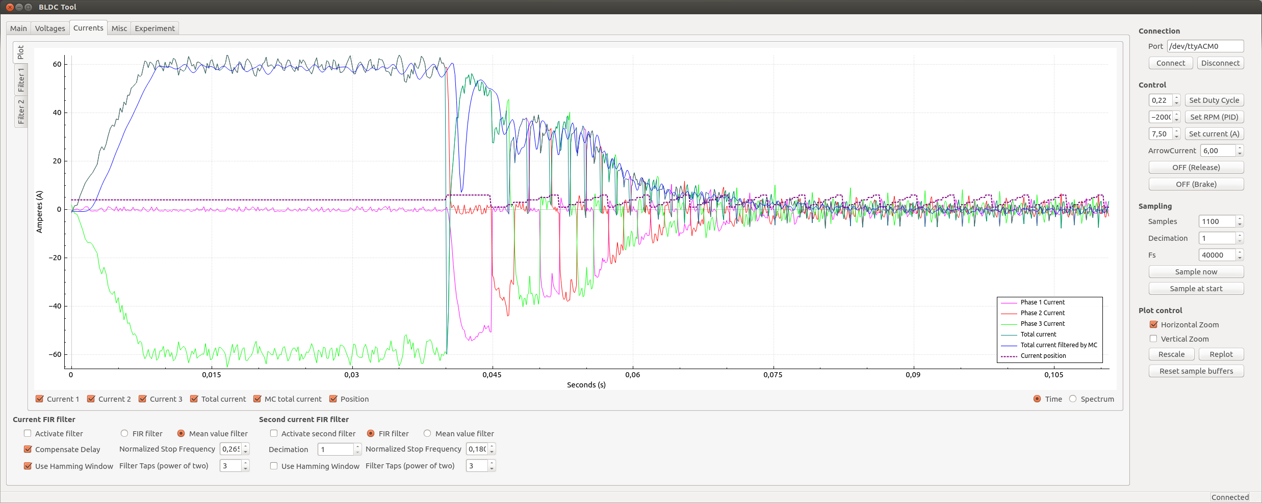
The first commutation happens to be exactly at a position where no torque is produced, which is as sub-optimal as it can get. On the current waveform, it can be seen that the current limit of 60A is applied. After 40 millisecond, the algorithm decides that nothing has happened for a too long time and adds an auto-commutation. After this, the motor is tracked right away and the commutations are nice and even. This works even though the motor was stalled with 60A for a while.
Here is one example where I start the motor, switch off power after a few commutations and then switch on power again:
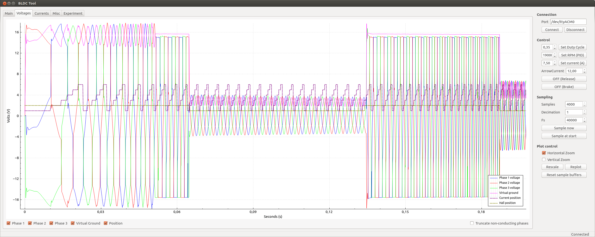
It can be seen that the un-driven back-emf is tracked perfectly while the power is gone and no commutation is missed or distorted during the transitions.
Results
The electric longboard I have been working on starts perfectly smooth without sensors (see the video above).
I have also tested this on a 700w hub motor on an electric bicycle with extremely good results. Full throttle from a complete stop is smooth and no problem at all. I don’t miss hall sensors here one bit.
Pingback: VESC – Open Source ESC | Benjamin's robotics
Does the non FOC implementation require two shunts? The reason I ask is that I am working with my custom designed ESC using a Freescale MCU but I have a single shunt implementation. I would like to have a high torque smooth start which is proving to be very difficult to achieve. I am obviously using a a BLDC brushless, sensorless motor.
No, when not using FOC one shunt on the input is actually better than using two on the phases since the software becomes simpler. Also, with only one shunt you can run at 100% duty cycle.
I have to go through your code yet so pardon me if you have addressed this.
“There is a parameter that defines the voltage coupling between the windings when measuring the back-emf. This make a huge difference when running at low speeds with low duty cycle.”
how was this parameter calculated?
And… You may have heard this before but… I love you ! 🙂
Hello Vedder,
I have the following queries.
1. Usually it is expected that Bemf is usable after the motor reaches 5% of its nominal RPM. You state that you are using closed loop from the first commutation. How is this possible even if the signal is clean the Bemf would be almost non existent right ?
2. What do you think is the optimal switching frequency per pole pair & RPM. Is there any rule of thumb? The real question is how many measurements are needed to calculate the area after zero crossing?
1. It depends on the type of motor. For most motors, a position-dependent part of the input voltage can be seen on the phase where I’m measuring the back-emf when the measurement is done during the on-time. These motors run fine even on 1% duty cycle or less. Other motors do need some speed before they have useful back-emf, but it usually works for less than 5%. Closed loop operation actually has some other conditions for commutation, so when there is not enough back-emf of the motor is not where it is expected, auto-commutation will be performed and it works out.
2. It depends. 10 samples or more are good, but is also works with two or three samples. There are always tradeoffs.
Hello, Vedder, thank you so much for sharing this wonderful design. I am particularly interested in the BLDC sensorless control part. However, when I read your code, I found it rather difficult to follow since there aren’t many comments. Is there any document I could refer to regarding the motor control part you implemented? Would you please elaborate more on the tricks you did to improve its starting performance? Thanks a lot!
“There are no hardware low-pass filters that introduce phase delay. ”
I noticed you used FIR filter, which also introduce phase delay as hardware filter, right?
The fir filters are not used for the phase voltages, but for other things. The current for example has one filtered version and one unfiltered version for different uses.
For now, this post and the code is the best I can provide. Writing documentation for how to make a new implementation takes a lot of time, and I have so many other things with higher priority now. If you are used to coding and know how to control BLDC motors in general, I think you can follow the code. If there is something specific in the code you don’t understand, you can ask me.
Hello,
I’ve got a question about BEMF difference during PWM ON and PWM OFF times,
http://i62.photobucket.com/albums/h119/7evgen7/ABController/BEMF%20non%20linearity_zpswqyozc86.png
How to handle this?
Integrating during off-time will have different threshold value than on-time
Hi,
You cannot integrate in the off time since the negative commutations will be truncated because the body diodes in the FETs will conduct for 3 of 6 steps.
I am switched OFF phase from -BUS to +BUS, this gives me avability to integrate during OFF time always. Actually it is toggle from -BUS to +BUS for every step
Then you can measure in the off period as well. You will get different voltages. If you vary the supply voltage it will also change the voltage that you see, even if you adjust the duty cycle to get the same motor speed. I noticed that this is a problem when running on low duty cycle, so I added a compensation factor than I called BEMF coupling. It makes a lot of difference on low speed. As far as I can tell the voltage difference you see between the on and off time is related to the dc bus voltage with a factor, and it is different for different motors.
Oh okay. As i can see for now OFF time integration threshold if more stable than ON time. So i used OFF untill 80% duty, after it’s switches to ON integration. Factor of difference between ON and OFF shoud be calculated during calibration, i think. Same for no-pwm integration, it is slighty different than OFF time (a bit less for my motor)
I actually measured the integration during no PWM and added compensation when PWM is on. The compensation is has the bus voltage as one parameter. I can only measure on the ON time since I don’t use bipolar PWM (although I have an option to do that) in order to get less switching losses and less ripple.
Well, it is not exactly bipolar. One phase have one switch constantly ON, other phase have PWM for both switches (low and high). Ripple and conduction looses should be same, but better heat distribution coz of alternating top-bottom constantly on-switch
alternating the switch that is constantly on sounds like a good idea, I didn’t think about that at all. The only disadvantage I see is when you have low side shunts like I have you won’t get as much time for the current to settle before sampling when the high side switch is on. I only have two shunts and take advantage of this for 4 out of 6 current samples, and at high duty cycle it makes a significant difference.
Yes, that’s why I have single low side shunt, with op amp installed, and frequency variation for low duty %. Also there is cons about discharging bootstrap capacitor on a top fet driver, you can’t hold some phase combinations for too long. For very low speed i made a 50% PWM = 0% duty. Both phases are PWMed. This helps to keep bootstrap capacitor charged, in a cost of more active losses (1/3 more). But this is only for veery low speed. Current ripple less than synchronious pwm i told you before, becoz of twice more current conduction times than PWM frequency.
By the way i’ve used your code as start-up a long time ago, so thanks here for sharing your work!
Hi Benjamin
VESC 4.10 is on the way, I can’t wait to try out FOC on both SK3 motor and 6″ hub!
I have a question : when the battery is fully charged and I want to be able to brake, does VESC support dynamic braking at least for the first hundreds of meters?
If not, do you plan on adding this function or are there technical problems for the implementation?
This could avoid me some hospital stays 🙂
Thanks for all your work
Hi E404,
The VESC does not know anything about “max voltage on your battery”. So if you live on top of a mountain and start your day riding down that mountain, then it is up to you to charge your battery to a level that remains below the max-charge-voltage of your battery.
Also, suppose you are riding down a 10% slope at 10m/s, you get a vertical speed of about 1m/s. If you weigh 100kg, that will produce 1kW of energy that needs to go back into the battery. That will surely exceed the charging limit of your battery.
Normally with smaller hills that won’t be a problem. But if you live say 600m above the valley floor and start by riding down, I think you need a big high-C pack just to be able to accept the charging currents on the way down…. (A 40C 10Ah battery usually has a 5C or 50A charging allowance. At 20V, that means it can actually accept that 1kW charging power! ).
At 720m above the valley floor, you HAVE to leave home with an empty pack, or otherwise you’d overcharge the battery on the way down. Above 720m above the valley floor you need a bigger pack, just to be able to store the energy that is braked into the battery….
NICE startup! especially on the carpet… wow
Hi Benjamin
Can I have a question: how to detect BEMF signal at startup stage? From open H/W design, I have not found out the circuits for this. Would you advice how?
Thank you
hey Benjamin,it s so great toshare this wonderful design. And I wanted to know do you have analysised any plot about FOC mode? Im eager to learn more about FOC
thank you!