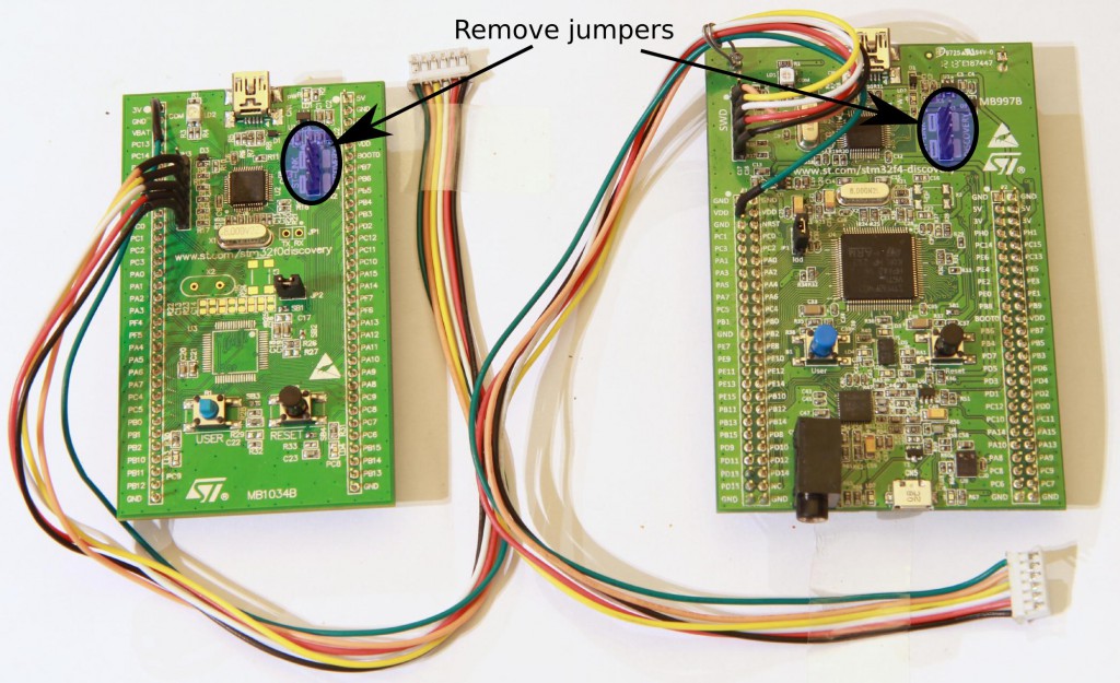
When I make custom STM32 PCBs (such as my RF-mote or my ESC), I use an SWD connector for programming and debugging the microcontroller. The connector is a 6-pin micro-jst connector with 2mm pitch, which easily can be found by searching on ebay. An STM32 discovery board with stlinkv2 works perfectly for programming and debugging, and can be connected as shown here (click on the picture to get a larger version where the wire colors can be seen):
Notice that I have removed two jumpers on the discovery board to disconnect the SWD from the microcontroller. The pins in the jst connector are ordered in the same way as on the discovery board, but the outermost (green) cable is connected to 3V or VDD.
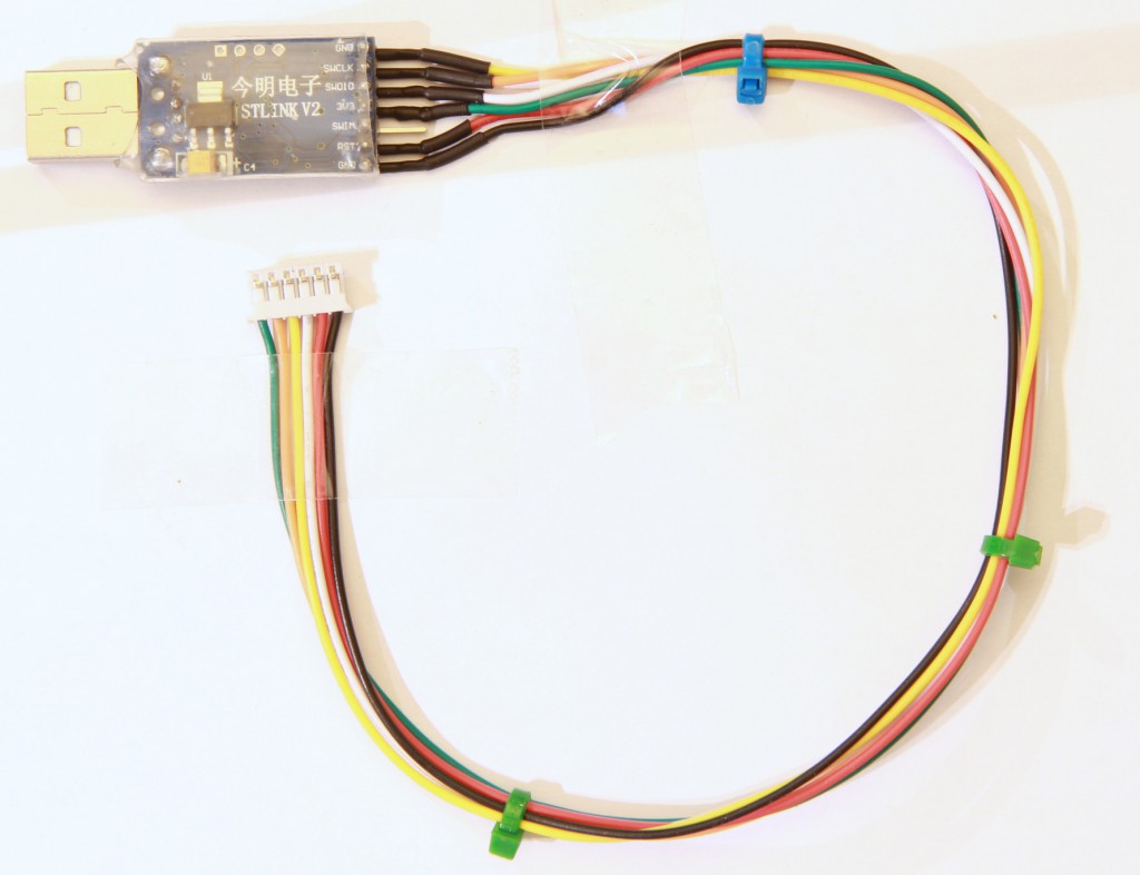
There are also some small and inexpensive stlinkv2 programmers available on ebay (just search for stlink v2), such as this one which I have soldered a micro-jst cable to:
Update:
I had some problems with too long JST cables. If uploading the program does not work for you, try shortening the JST cable.


You can use a 4 wire SWD connector. SWD-GND-SCK-VDD are enough for normal programming and debugging. STLink v1 had only those 4 connections, and its the programmer I use daily, despite its horribly broken usb firmare.
Furhermore, the VDD wire can be removed if you short it to VDD inside the programmer.
This could save you some pcb area in the future.
Pingback: A Contiki port for my custom cc2520+stm32f4-boards | Benjamin's robotics
One thing that’s bitten me repeatedly using the discovery boards as programmers is that removing the jumpers isn’t sufficient to use the SWD programming header – the NRST pin is still connected to the discovery target mcu. Either leave the pin unconnected to the board you’re programming (undesirable as having hardware reset control can allow you to program a chip that’s locked up), or undo the solder bridge on the underside of the board to release the pin.
On the stm32f4discovery board the bridge is marked SB11.
Which software do you reccomend for programming with STlink v2?
In which compiler did you program VESC software, so it can be opened/edited directly as it is?
Thanks,
Gregor
openocd. I used eclipse and a makefile project.
I’m getting an error in the Make Build step:
Info : STLINK v2 JTAG v17 API v2 SWIM v0 VID 0x0483 PID 0x3748
Info : Target voltage: 2.907583
Error: init mode failed
in procedure ‘transport’
** OpenOCD init Failed **
shutdown command invoked
#openocd -f board/stm32f4discovery.cfg -c “reset_config trst_only combined” -c “program build/BLDC_4_ChibiOS.elf verify reset” # For openocd 0.9
Do you have any guidance?
Thank you,
DougM
I have this same error, though the target voltage is different.
even i got the same error please help
Ebay link for jst has typo. Thanks for your great vesc.
I forgot to mention that I compiled BLDC Tool successfully on mac (that has Qt dependencies installed) after modifying some UI stuff for Qt5. Most of the GUI components now seem to be on QtWidgets package and QApplication::translate does not have UTF8 as a parameter on Qt5. With those few changes it compiles nicely against Qt5 on Mac.
I have the same error as Doug above. Updating openocd gives more info:
====
1:16pm > make upload
#qstlink2 –cli –erase –write build/BLDC_4_ChibiOS.bin
openocd -f interface/stlink-v2.cfg -c “set WORKAREASIZE 0x2000” -f target/stm32f4x_stlink.cfg -c “program build/BLDC_4_ChibiOS.elf verify reset”
Open On-Chip Debugger 0.10.0-dev-00185-g32bb775 (2015-12-31-13:15)
Licensed under GNU GPL v2
For bug reports, read
http://openocd.org/doc/doxygen/bugs.html
0x2000
WARNING: target/stm32f4x_stlink.cfg is deprecated, please switch to target/stm32f4x.cfg
Info : auto-selecting first available session transport “hla_swd”. To override use ‘transport select ‘.
Info : The selected transport took over low-level target control. The results might differ compared to plain JTAG/SWD
adapter speed: 2000 kHz
adapter_nsrst_delay: 100
none separate
Info : Unable to match requested speed 2000 kHz, using 1800 kHz
Info : Unable to match requested speed 2000 kHz, using 1800 kHz
Info : clock speed 1800 kHz
Info : STLINK v2 JTAG v17 API v2 SWIM v4 VID 0x0483 PID 0x3748
Info : using stlink api v2
Info : Target voltage: 3.289544
Error: init mode failed (unable to connect to the target)
in procedure ‘program’
in procedure ‘init’ called at file “embedded:startup.tcl”, line 473
in procedure ‘ocd_bouncer’
** OpenOCD init failed **
shutdown command invoked
====
I’ve tried it with and without the USB cable connected. I suspect the “unable to connect” indicates a hardware error, presumably in my soldering, unless anyone has other ideas.