================= IMPORTANT UPDATE =================
I have written a new post about my open ESC on this page and also updated the hardware significantly. If you haven’t built it yet and if you are planning to order parts for it, please refer to that page. I will only leave this page for reference in case you have built it before I wrote the new post and updated the hardware. Also, If you have built the ESC before, the tutorial and software on the new page also applies to the old hardware.
=====================================================
Updated 2014-12-08
For about three years I have been working on a custom BLDC motor controller (also known as an ESC). I have spent hundreds of hours on writing code and I have made many minor and four major revisions of the printed circuit board (PCB). Now I finally have something that I can publish. The code can still be cleaned up a lot, especially the latest parts that I wrote in a hurry, but I don’t want to delay the release forever.
The features of this BLDC controller are:
- The hardware and software is open source.
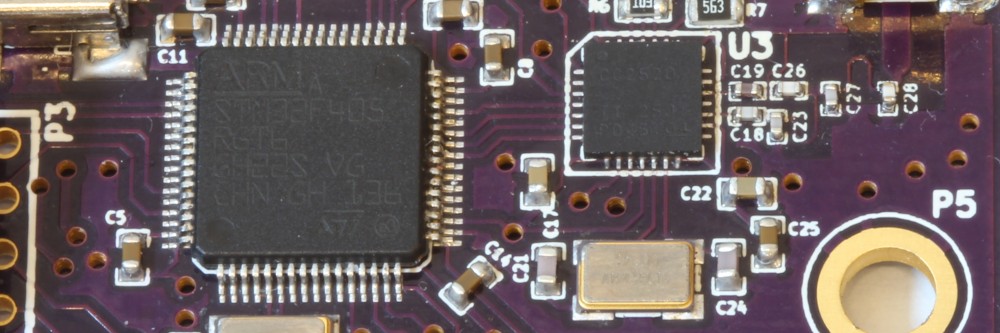
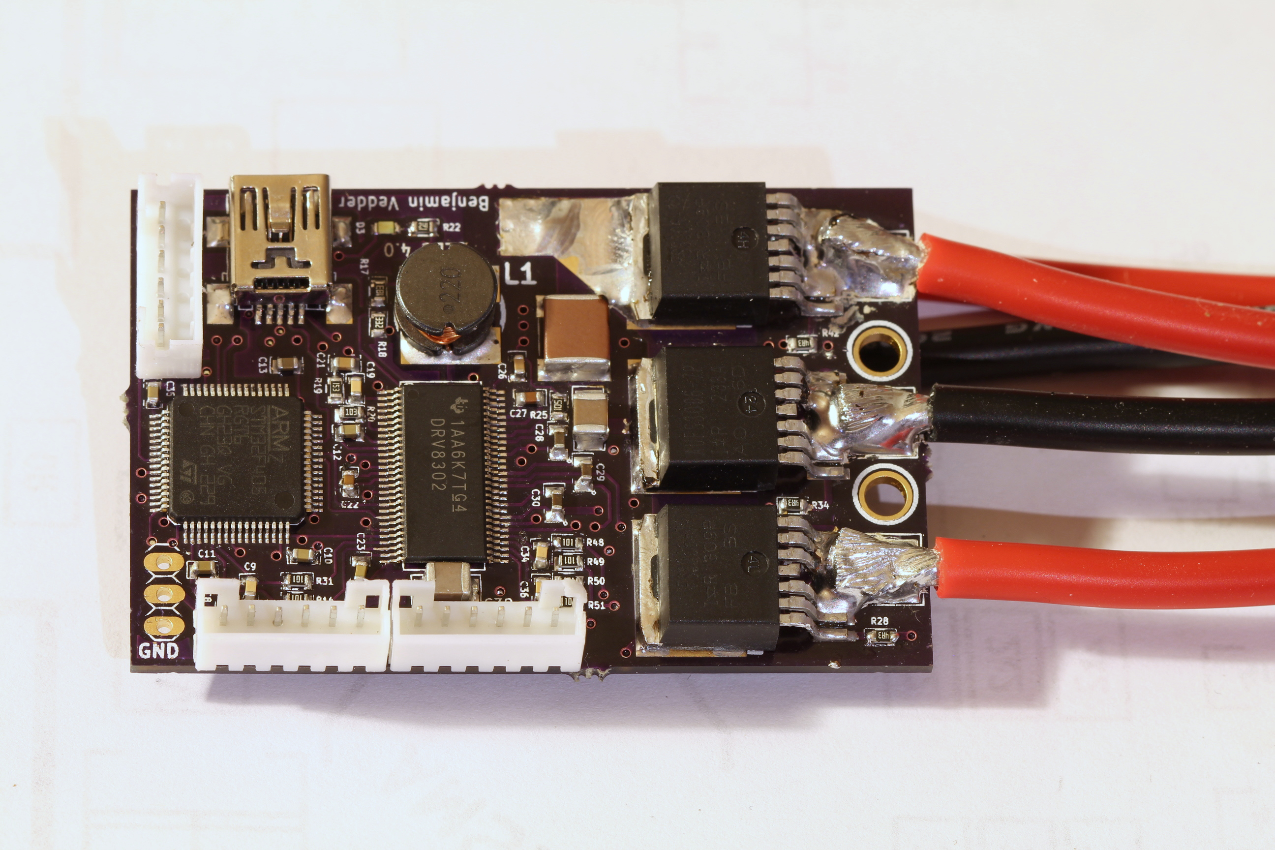
- A STM32F4 microcontroller.
- A DRV8302 MOSFET driver / buck converter / current shunt amplifier.
- IRFS3006 MOEFETs.
- 5V 1A output for external electronics from the buck converter integrated on the DRV8302.
- Voltage: 8V – 60V.
- Current: Up to 240A for a couple of seconds or about 50A continuous depending on the cooling.
- PCB size: slightly less than 40mm x 60mm.
- Current and voltage measurement on all phases.
- Regenerative braking.
- Sensored or sensorless commutation.
- Adaptive PWM frequency to get as good ADC measurements as possible.
- RPM-based phase advance.
- Good start-up torque in the sensorless mode (and obviously in the sensored mode as well).
- The motor is used as a tachometer, which is good for odometry on modified RC cars.
- Duty-cycle control, speed control or current control.
- Seamless 4-quadrant operation.
- Interface to control the motor: servo signal, analog, UART, I2C, USB or CAN (with a transceiver). Some of these modes need a bit more code to work, but not much.
- Servo signal output. Good when e.g. controlling an RC car from a raspberry pi or an android device.
- The USB port uses the modem profile, so an Android device can be connected to the motor controller without rooting. Because of the servo output, the odometry and the extra ADC inputs (that can be used for sensors), this is perfect for modifying a RC car to be controlled from Android (or raspberry pi).
- Adjustable protection against
- Low input voltage
- High input voltage
- High motor current
- High input current
- High regenerative braking current (separate limits for the motor and the input)
- Rapid duty cycle changes (ramping)
- High RPM (separate limits for each direction).
- When the current limits are hit, a soft back-off strategy is used while the motor keeps running.
- The RPM limit also has a soft back-off strategy.
- The commutation works perfectly even when the speed of the motor changes rapidly. This is due to the fact that the magnetic flux is integrated after the zero crossing instead of adding a delay based on the previous speed.
- When the motor is rotating while the controller is off, the commutations and the direction are tracked. The duty-cycle to get the same speed is also calculated. This is to get a smooth start when the motor is already spinning.
- All of the hardware is ready for sensorless field-oriented control (FOC). Writing the software is the remaining part.
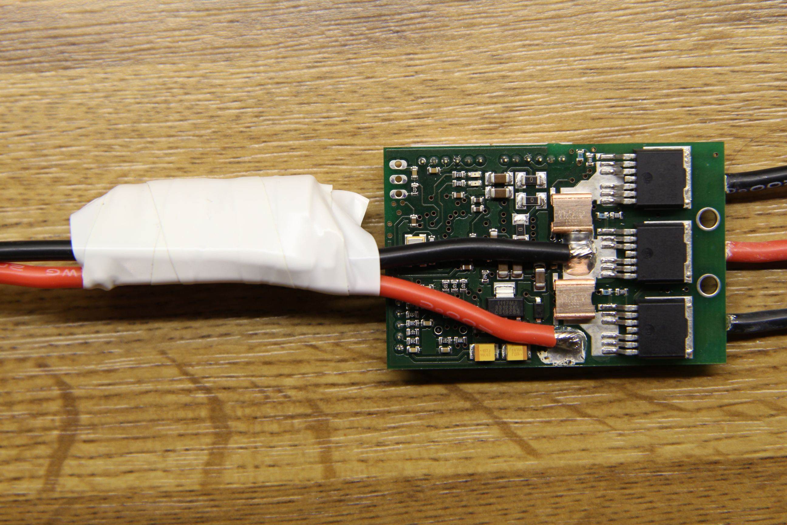
This is a photo of the front of the assembled PCB (please ignore the soldering quality…):
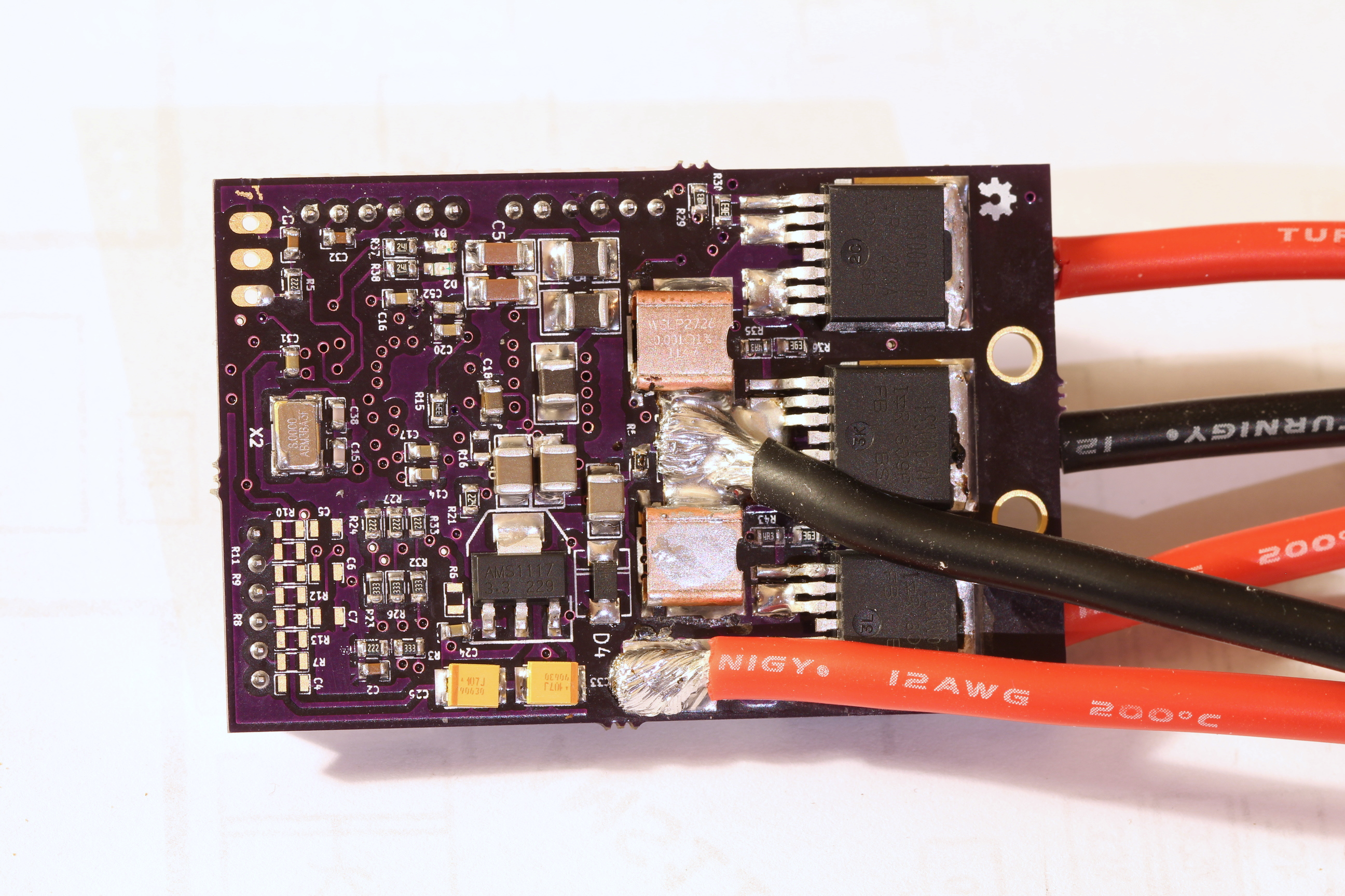
This is the back:
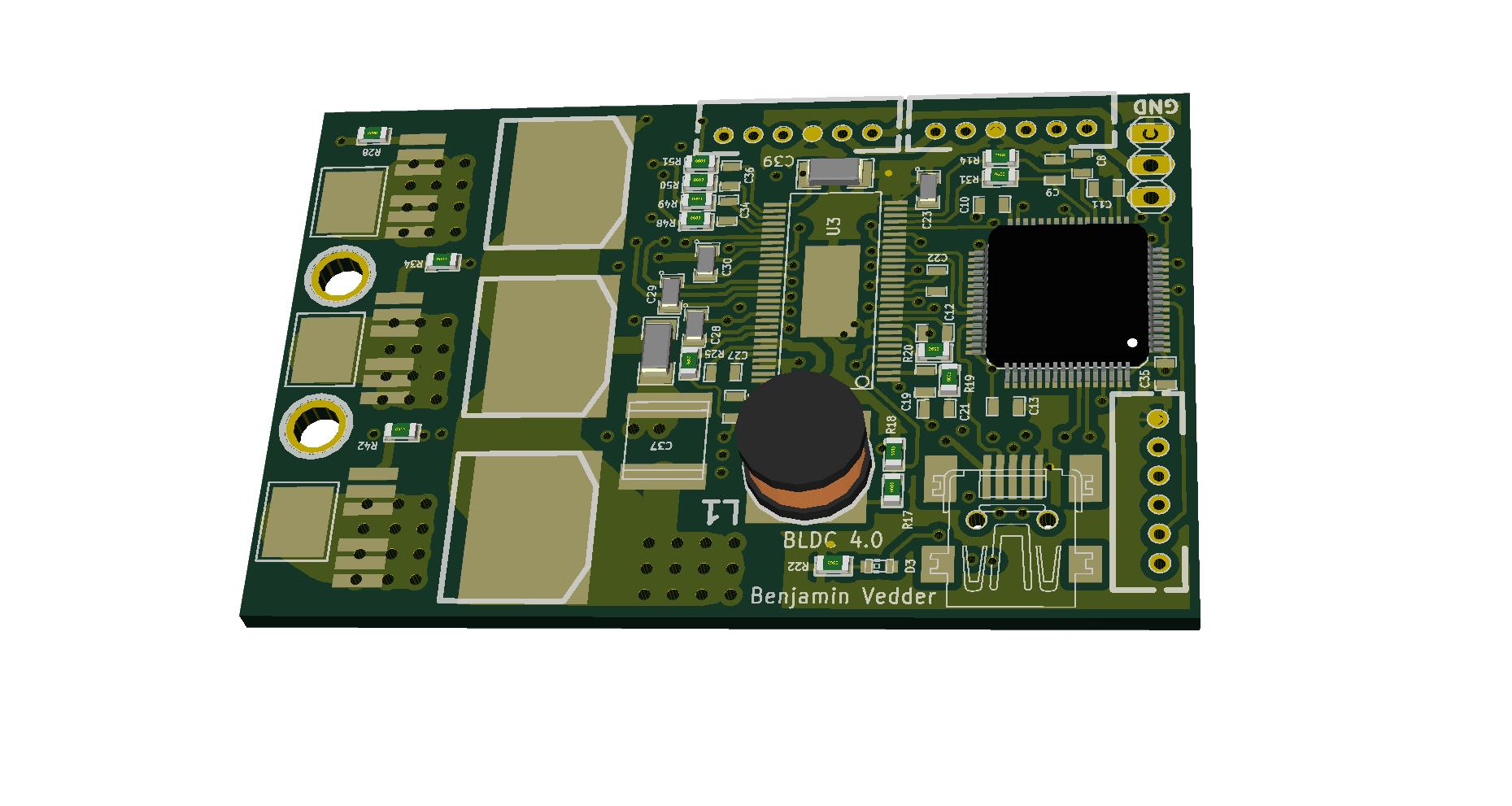
An image from the KiCad 3D-viewer
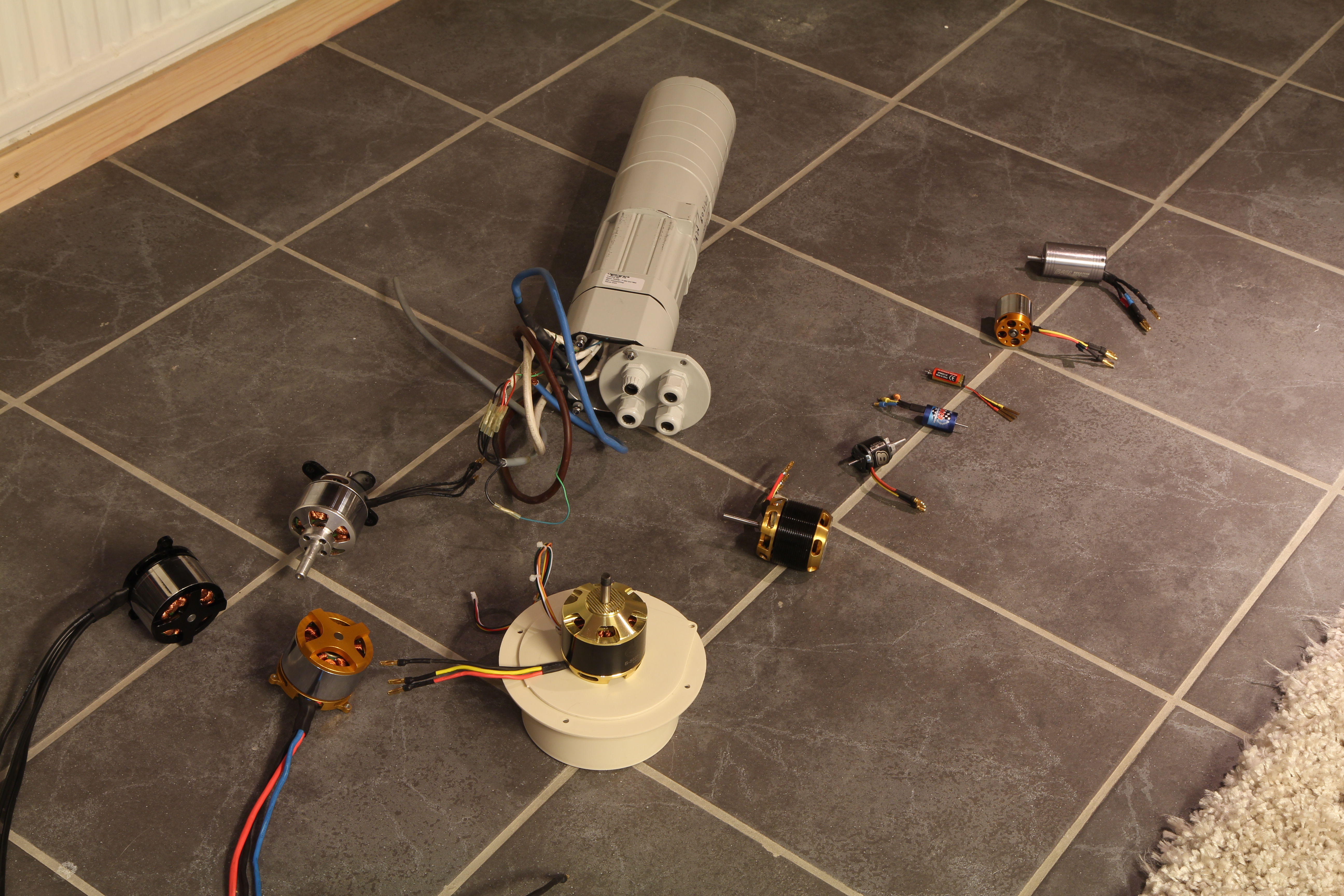
I have tested the following (and more) motors in sensorless mode and achieved good startup torque:
Issues and updates
Before presenting the details of the hardware design, I will present some notes and updates that have come to my attention while testing the motor controller. There are also some people worldwide who have rebuilt my motor controller and got it working after I helped them a bit, so I have also added the issues they have encountered here.
* UPDATE * I replaced the 3.3V regulator with the TC2117-3.3VDBTR and got rid of a few problems. The dropout voltage on the other regulator was probably too close to the difference between 5V and 3.3V, so sometimes the 3.3V supply would drop.
* IMPORTANT UPDATE * Replace L2, L3 and L4 with 0 ohm resistors. Otherwise, the DRV8302 will keep dying randomly. NOTE: This is fixed in the latest hardware versions on github. I strongly suggest that you use one of them.
* UPDATE * If the motor controller resets when drawing large current spikes, the cause can be that the buck converter shuts down for a while. I noticed this on my RC car when I set the current limit to 150A. I solved that by removing C26 from the SS_TR pin on the DRV8302. This will disable the slow start feature of the buck converter, which makes it start up fast enough after shutting down for the microcontroller not to shut down. I don’t know if this is a proper solution, but it has been working for the few hours I tested the RC car without problems.
* NOTE * The pad under the DRV8302 has to be soldered. If it isn’t, the motor controller will not work for sure. The pad is not just for thermal cooling, it is also the only ground of the DRV8302.
* NOTE * There are no electrolytic capacitors on the PCB, only small ceramic ones to handle high frequency noise. However, there should be rather large electrolytic capacitors close to the motor controller on the DC bus. I chose not to put them on the PCB to make design a bit more flexible. For example, one can add capacitors like this:
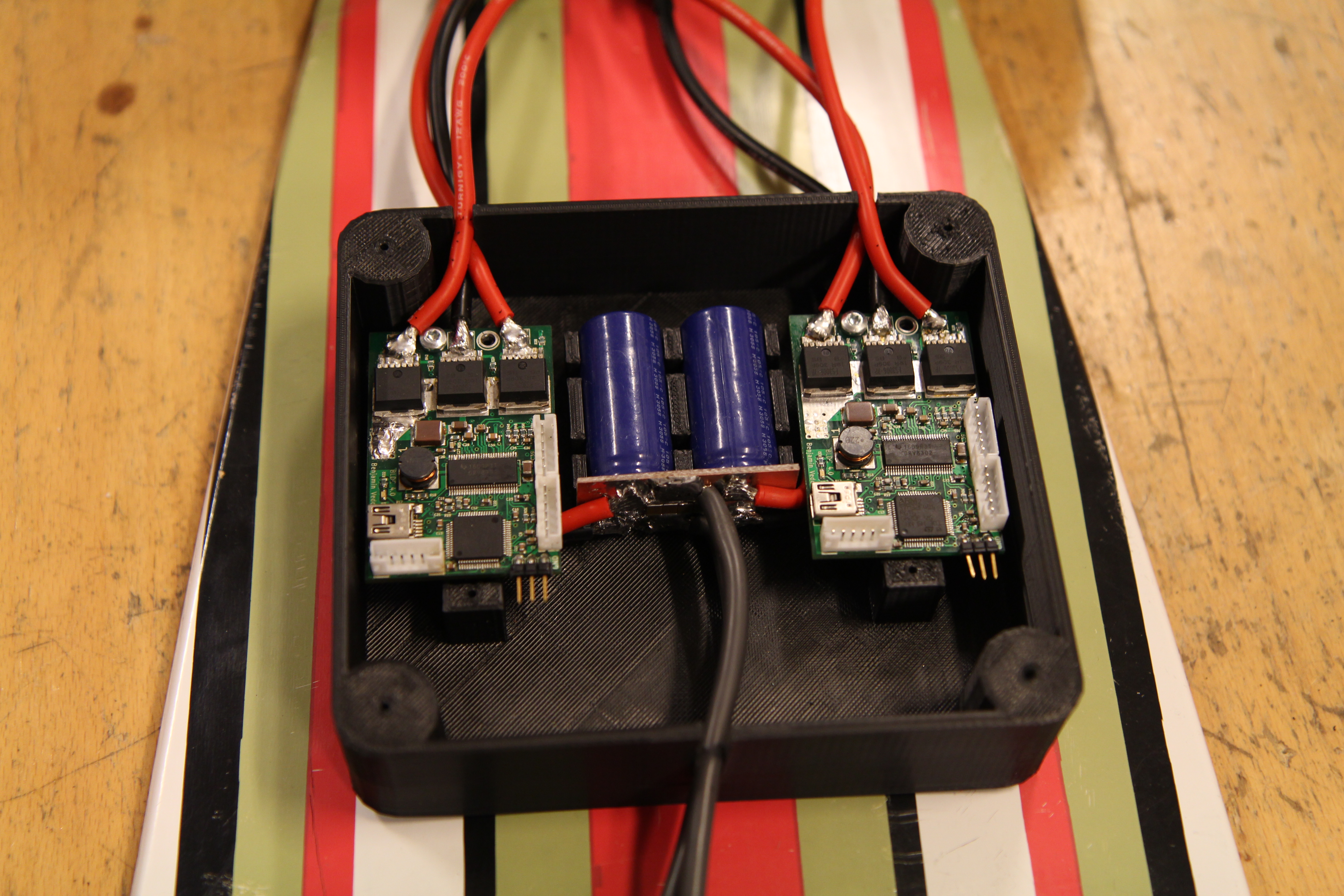
for a multicopter, it might be a bit more convenient to put a capacitor on the cable like this:
Hardware design
IMPORTANT UPDATE: A new version of the hardware can be found here: https://github.com/vedderb/bldc-hardware I will write a new post about that and the large amount of recent updates soon. If you want to build this motor controller, please use the hardware from this github link since it has many important fixes and features. There is also a new BOM linked from github.
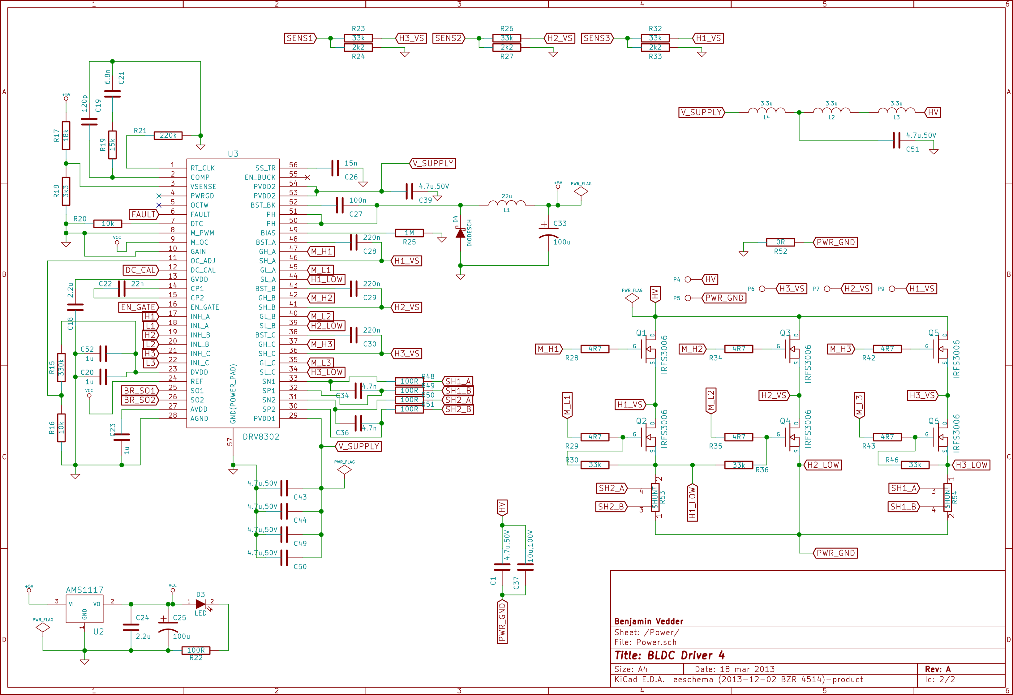
The PCB has four copper layers and is designed with KiCad. The size is slightly less than 40mm x 60mm. This is the schematic (a PDF can be downloaded here):
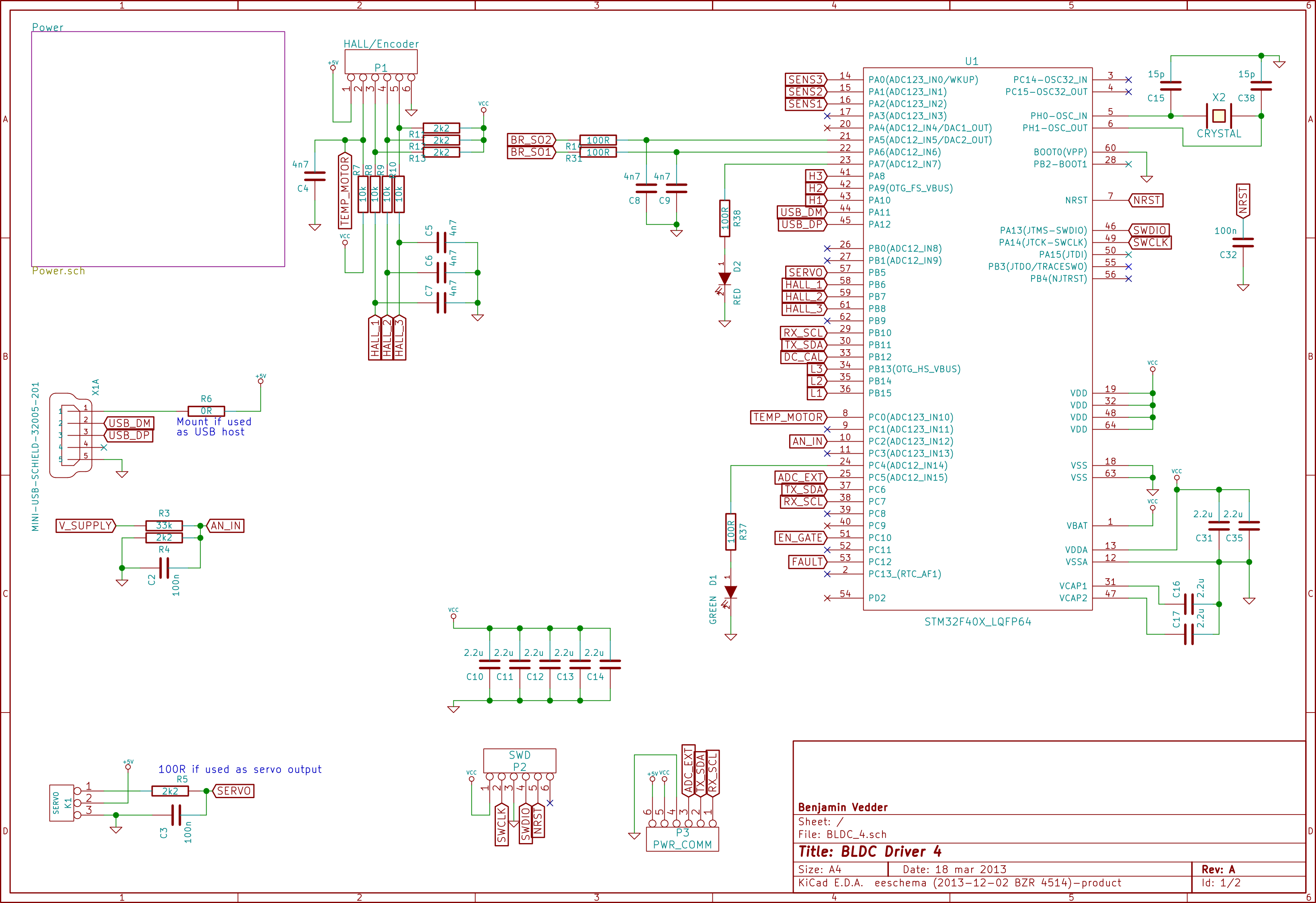
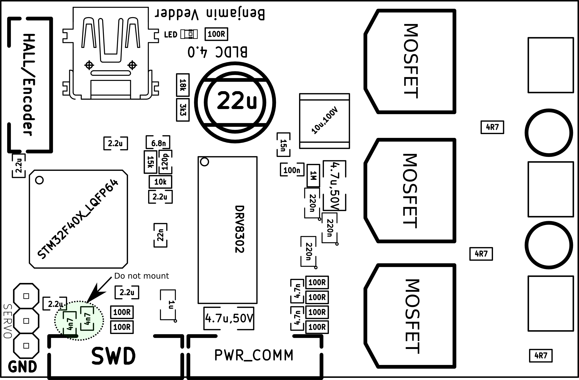
The component positions and their values on the front:
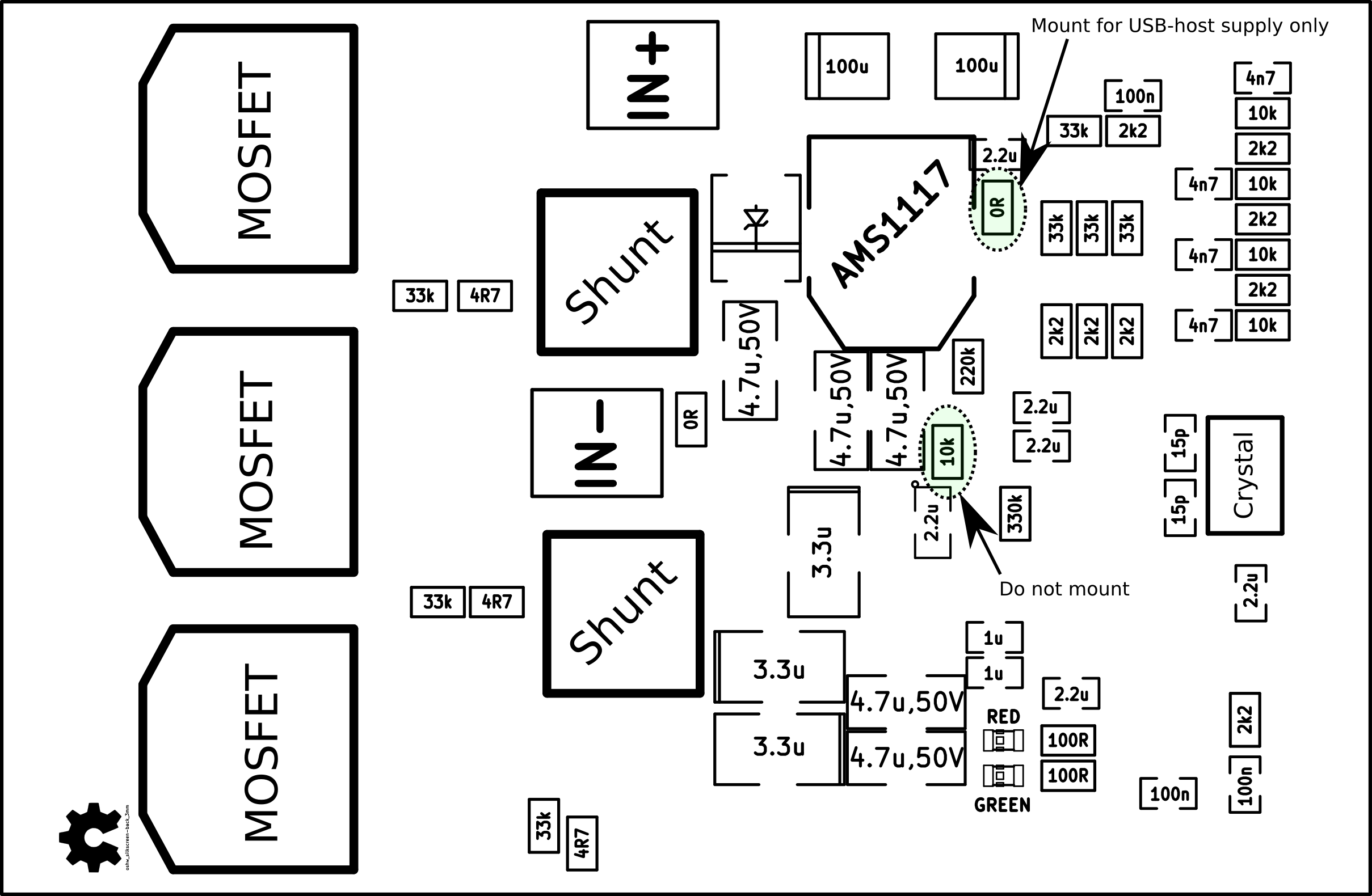
On the back:
A BOM with mouser part numbers can be accessed via google docs:
The KiCad-files can be downloaded here. If you are missing any KiCad libraries for this project, they can hopefully be found here.
PCB service
- The PCB-service from Hackvana works well for this PCB. In this case, use the following gerber files: BLDC4_Hackvana_v1.2
- The PCB service from OSH park also works well. In that case, use these gerber files: BLDC4_OSH_Park
Software overview
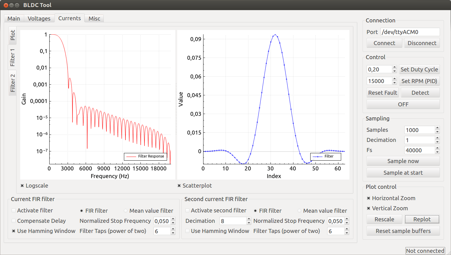
The software consists of a ChibiOS-project for the STM32F4 and a Qt-program to test and debug the hardware. This is what the FIR filter design part of the Qt program looks like:
It is possible to plot the currents, voltages and the duty cycle in real-time. This is useful when debugging how everything behaves when e.g. the software current limits are hit while loading the motor. Data can also be sampled and stored at a high rate internally and then sent to the Qt program for plotting high-speed processes such as the commutation timing. Here is a screenshot of the program displaying the commutation timing:

Note that the hall sensor position in the screenshot above is constant because there are no hall sensors connected. When adding custom hall sensors to BLDC motors, their position can be adjusted by comparing their output to the estimated rotor position in sensorless mode. Plotting the hall sensor position while running the motor in sensorless mode is therefore very useful.
Software set-up
The STM32 code for the BLDC controller can be downloaded here. In order to build and run it, ChibiOS with the ST libraries and a minor modification is required – you can download it here. To set up the required toolchain you can have a look at this post.
The Qt program can be downloaded here. To build it on Ubuntu (tested on 13.10), run:
sudo apt-get install qtcreator qt-sdk qmake make |
Now you should be able to start the program and connect to the motor controller.
A short tutorial to run a motor
In this section I will describe how to run an outrunner motor in sensorless mode from Ubuntu Linux. The reason for using an outrunner is that the parameters in the github project are tuned to work with most of my outrunners that I have at home. Adjusting MCPWM_CYCLE_INT_LIMIT in the mcconf file can affects the timing and should be tuned for each individual motor.
Note: The start-up torque in sensorless mode is higher than on most sensorless hobby ESCs, but the algorithm to start the motor will cause a delay before closed-loop commutation can be used. This delay is not desirable when e.g. building a sumo robot such as this one, so in such applications a sensored motor and the sensored mode is recommended.
Required steps
- Add your user to the dialout group as described here. Log out and log back in. This is done in order to access the serial port emulated by the USB interface of the motor controller.
- If you don’t any 3g modem on your computer, remove the modemmanager package. This is because otherwise there will be many seconds delay before the Qt program can access the USB port since modemmanager is interfering (I’m sure that this can be solved in some other way).
benjamin@benjamin-UX31A:~$ sudo apt-get remove modemmanager
- Install a toolchain for compiling and uploading the STM32F4 code. See this post for a tutorial.
- Download the ChibiOS-version with a minor USB modification: ChibiOS-RT-master. This modification disables the voltage sensing on the VBUS pin because that pin is used for something else.
- Compile and upload the program to the motor controller. How to use a discovery board as a programmer can be seen here.
- Assemble the PCB. The component position sheets above are very useful for that.
- Connect the outrunner motor and a power supply to the BLDC controller.
- Download the STM32 code here. Set the path in the makefile to where you have extracted ChibiOS. Compile and upload the program.
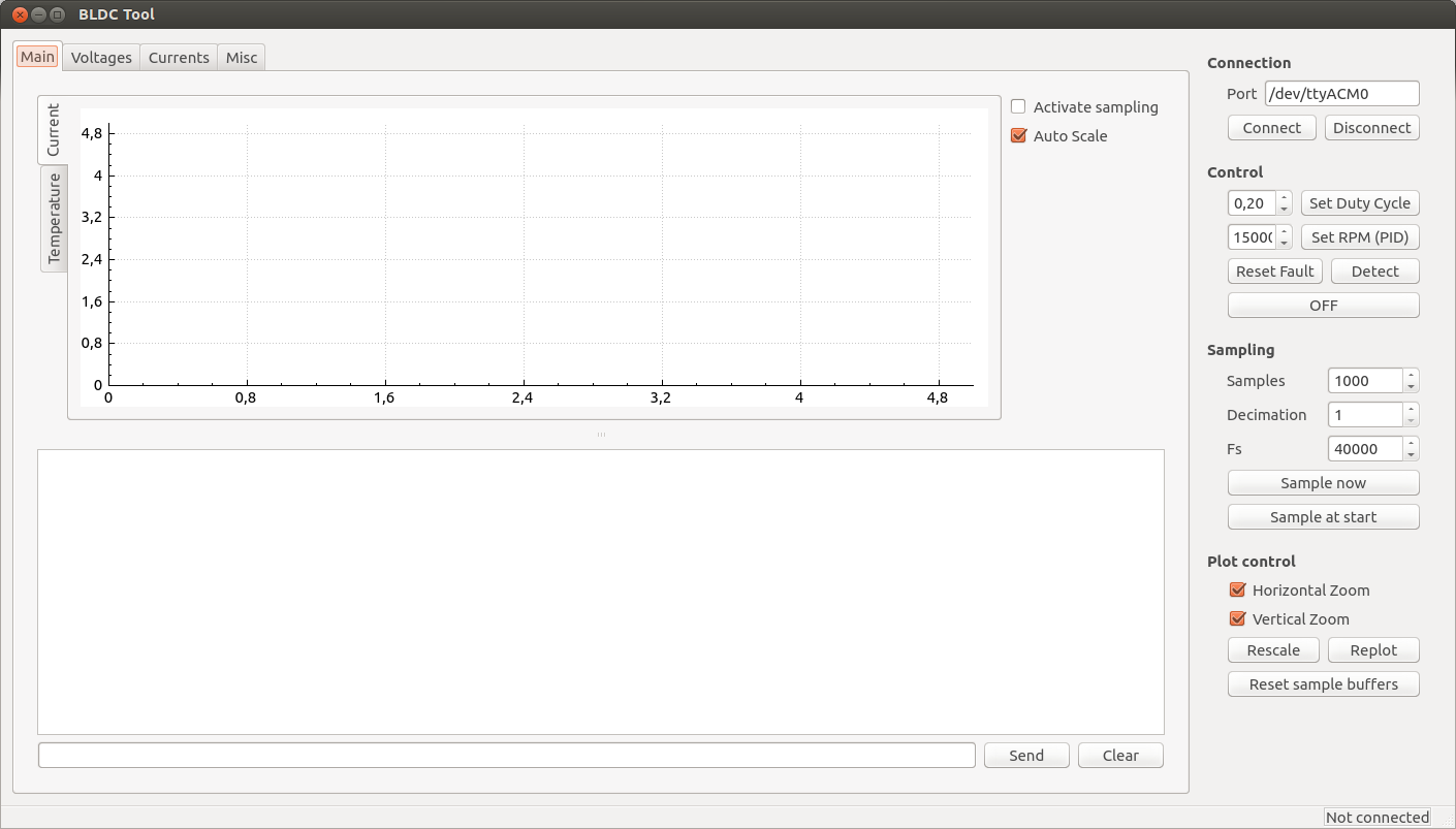
- Compile and start the Qt BLDC tool as described above or on the github page here. A window like this one should appear:
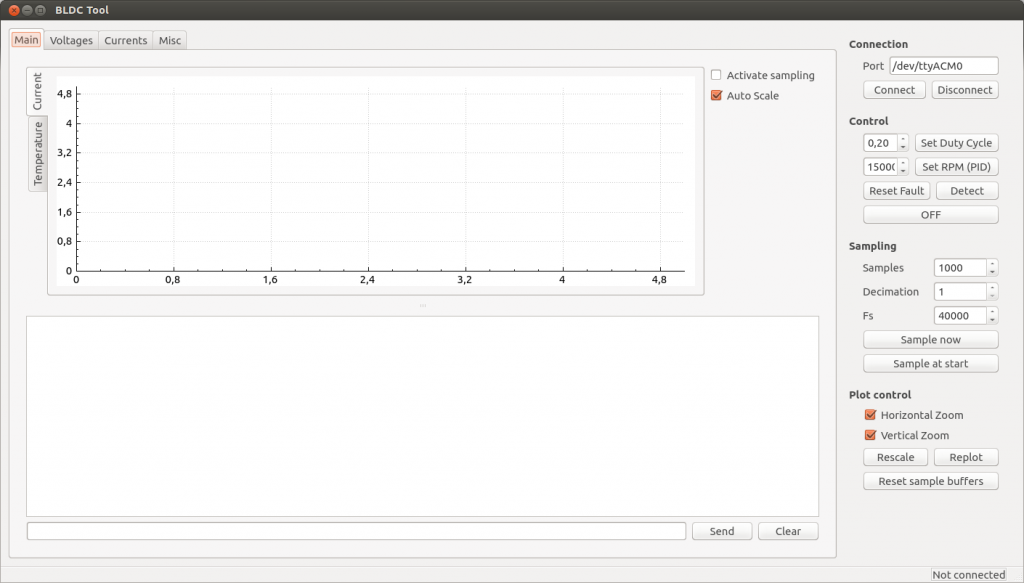
- Make sure that the USB cable is connected and the correct port is chosen in the tool, e.g. /dev/ttyACM0. If you have other devices that show up as serial ports, the BLDC controller might get another one such as /dev/ttyACM3. See the dmesg output when connecting the USB cable to see which device is assigned to it:
benjamin@benjamin-P5K:~$ dmesg | tail
[ 8198.248058] usb 1-5.3: new full-speed USB device number 6 using ehci-pci
[ 8198.357182] usb 1-5.3: New USB device found, idVendor=0483, idProduct=5740
[ 8198.357185] usb 1-5.3: New USB device strings: Mfr=1, Product=2, SerialNumber=3
[ 8198.357188] usb 1-5.3: Product: ChibiOS/RT Virtual COM Port
[ 8198.357191] usb 1-5.3: Manufacturer: STMicroelectronics
[ 8198.357193] usb 1-5.3: SerialNumber: 270
[ 8198.395006] cdc_acm 1-5.3:1.0: This device cannot do calls on its own. It is not a modem.
[ 8198.395038] cdc_acm 1-5.3:1.0: ttyACM0: USB ACM device
[ 8198.395503] usbcore: registered new interface driver cdc_acm
[ 8198.395506] cdc_acm: USB Abstract Control Model driver for USB modems and ISDN adapters
- Connect to the BLDC controller with the connect button. The lower right corner of the GUI should say Connected.
- Use the right and left arrow keys or the buttons in the GUI to run the motor. Activate the real-time sampling (with the checkbox in the main tab) to see the currents etc. in real time.
- Study the code and use/adapt the interfaces for your own application.

Cool!
Vad kör du för teknik för estimering av rotorposition?
Lite sugen på att bygga nått liknande själv
//O
När motorn kör mäter jag nollgenomgångar på fasen som inte är inkopplad. Efter nollgenomgången integrerar jag arean under fasen till en viss tröskel (tröskeln är inte beroende av hastigheten, men unik för varje motor) och kommuterar sedan. Eftersom arean ökar snabbare ju längre bort man är från nollgenomgången så spelar det inte så stor roll om man missar nollan lite. ADC-kanalerna är synkroniserade till PWM-signalen, så det behövs inga lågpassfilter som vrider fasen på signalerna.
Vid uppstart kör jag just nu en algoritm som kommuterar på ett varierande sätt tills en nollgenomgång åt rätt håll hittats och sedan byter jag till closed loop. Det ger nästan lika bra vridmoment som med sensorer, men det tar ca 0.5 sekunder innan positionen hittas. Jag jobbar på att mäta induktanserna i lindningarna innan start för att räkna ut positionen och börja kommutera på rätt ställe direkt.
Nästa steg är FOC.
/Benjamin
Hi,
Thank you for sharing.
I may implement an ESC soon and would likely base it on your own design. That would be FOC and with regenerative breaking.
Med vennlig hilsen,
Cyril
Hi Cyril,
That sounds interesting! FOC is my next step after I have finished implementing more protection features for the current software. I have a test bench with a motor connected to a high-resolution rotary encoder and a program where the ADC-sampling, PWM-channels etc is set up for FOC. First I will make it sensored and then try to make an observer that is able to track the rotor position. When that is done, I will run the same algorithm sensorless based on the observer. Regenerative braking is also a feature of course.
/Benjamin
Really Cool! Have you thought fo making it to an real product?
Thanks! I have thought about that, but I don’t really know how.
The past days/weeks I have been implementing a lot of new features:
https://github.com/vedderb/bldc/commits/master
The next step I plan is to write a post describing all features and have videos demonstrating them. Then, if there is enough interest from the community, I will try to proceed somehow.
Hi Benjamin,
I was looking for an open source BLDC controller and I found your very interesting post.
I’m interested for a sensorless sinus controller.
You say that the HW is ready for sensorless FOC but if I look to the schematics I can’t found the current sensor to measure the phase current, necessary for the FOC.
I’m not an expert in motor control, and maybe you can clarify me some concept.
The two negative MOS current shunt measure effectively the phase current in case of the BLDC motor is controlled in a trapezoidal mode.
The FOC is a sinusoidal control, so the shunts measures after the down MOS are not the image of the phase current.
So I have doubt about your affirmation: “the HW is ready for sensorless FOC”.
What do you think, I’m right or I have misunderstanding the concept of the FOC and phase current measure in sinus mode?
How do you think implement the FOC whit your HW configuration?
I hope one day to be able to give also my contribution to the open source community!
Hi Ivan,
When running FOC, all three half-bridges will be active with different duty cycles. This means that (unless the duty cycle is exactly 100% or exactly 0%) in the beginning of the PWM cycle all high-side MOSFETs will be ON and in the end of the cycle all low side MOSFETs will be ON. What I will do when running FOC is to sample all currents in the end of the PWM cycle when all low side MOSFETs are conducting. This means that when I sample the currents, I will sample the phase currents since they will go through the low side MOSFETs. This is the way the DRV8302 is intended to be used as far as I can tell, since it does not support connecting the shunts to the phases because of the voltage offset when the high side MOSFETs are on. Does this make sense?
/Benjamin
Hi Benjamin,
Wow, its very noble and very helpful thing you have done!. Thanks.
I have one modification I want to make. I want to have continuous current of 120Amps, Can I just change the Mosfets?
thanks naveen
Hi,
As far as I know, there are no MOSFETs available with the same voltage and lower ON-resistance in the same package (not significantly lower at least). You can achieve 120A with the same MOSFETs though, if you are able to cool them in a better way. One method would be to change the PCB layout so that all FETs are on the same side and a heatsink can be added from below with a good thermal connection by lots of vias.
Another way that might work would be to mount the PCB in a lot of airflow. If you have a multicopter for example, you could mount the motor controller close to the motor under the propeller. If you have some kind of EV, you could use a fan. I haven’t tested this though, so I don’t know if airflow alone is enough.
/Benjamin
120 Amps means you get problems with the legs on the FET’s – I use some stating 110A, but it is no way the legs can take that. To support higher current you probably should consider an array – FET’s in parrallell – get lower current per FET . this will also help your heat issue, but the board would get bigger
How about adding a issolated RS485 or providing a UART extension port this? I notice you use ESC, but it would be far more interesting using one of the UART’s to code a RS485 multidrop protocol to run several motors in a network.
There is an extension port with UART/I2C, an ADC-pin, 3.3V, 5V and GND. The USB port also shares the CAN-pins, has 5V and GND, so a tiny CAN transceiver PCB can be connected to the USB port. My plan is to make some different small extension PCBs to add isolated UART/RS485 or CAN-bus. This way, I can choose the extension PCB based on my application.
Wonderful project! I read/watched a tutorial about how the TI (Texas instruments) have done it. Thought to make something like this, but now I’m happy to find it here. Just a question (before i read the manual): It seems that the Qt BLDC tool helps to calculate specific parameters (for the motor connected). Does it upload them via the ttyACMxx interface ? If it does, is it possible to put them later in the source.
Which theory your algorithm is based on ? To me it looks like it’s close to one which TI described.
Thanks 🙂
Good observation. This approach is very similar to the one described by TI. In addition, I have adaptive switching frequency and phase-advance based on the rotational speed of the motor. There are also some tricks for startup and many protection features.
The UI is not able to upload any parameters (yet), I only use it to plot stuff and control/debug the motor controller. The main parameters that can be estimated using the UI are the low-speed and high-speed flux integrator limits. When plotting the voltages, it is possible to see if the commutations are too early or too late and this information can be used to change these parameters in a trial-and-error way. I haven’t made any description on how to do that yet, but I will hopefully do that soon.
hi:
i am a guy from china.i have read you comment,that you have mention ” tutorial about how the TI (Texas instruments) “.can you share me the tutorial that you have mention,or the wedsite.thanks a lot. my e-mail address is shifm_od@163.com.thanks again.
Hey there!
Firstly, nice controller!!! So well executed!
I am building my own custom BLDC controller for a university project. The project originally used stepper motors but these are unable to provide high power (~1000watt) so we are moving to BLDC, but would still like to have a similar positional accuracy and repeat ability as the steppers.
We are using the Texas Instruments InstaSpin-FOC and InstaSpin-MOTION enabled C2000 Piccolo micros, and the DRV8301 (similar to what you are using but with SPI interface).
Was wondering why you did not use the TI microcontrollers as these have built in Field Oriented control functions and take care of having to write the software to do so. We plan on recreating your controller but with a TMS320F28068MPN microcontroller instead.
Also just wondering why you only used two current shunts? I know the DRV8302 only has two current amps but doesnt FOC require all three? We plan on using a third external current amp and third shunt.
Again such impressive work!
Cheers!
Hi,
Thank you for the good feedback!
The most difficult part to develop for sensorless FOC is the rotor angle estimator that is hidden in ROM on the TI piccolo, so using it would make all my development depend on this single hidden algorithm. Right now I have the knowledge to easily replace any part of my motor controller with parts from another vendor and still get the same features, and I want to keep it that way. I am working on this project to learn how to do motor control, not to learn how to interface TIs hidden algorithm, an algorithm that I can’t study the internal workings of. A future goal for this particular project is to write my own rotor flux/angle estimator and use it for FOC. This way I will become an expert on FOC and have the ability to implement a motor controller with almost any microcontroller/rtos/hardware combination I like.
Regarding the current measurement: The current on the third phase can be derived from the other two phase currents, and my goal with this PCB was to make it small enough to fit in some robots, so it does the job. I think I will make another motor controller with better current sensors on all phases (and not below the switches) to really make a good development platform for motor control.
I do understand why TI don’t want to spend a lot of resources and effort on developing an algorithm and give this work away to the competitors for free, but I don’t want to get locked in by them. It really is a shame that the structure of our society makes it so beneficial for us to hide information from each other and that there is a need for patents, copyright, anti-piracy etc. This makes my motivation drop a lot.
/Benjamin
Excellent project following with great interest , and time to get the soldering iron out !
/Dave
Hi, Great job with the ESC. I was just wondering if it would be possible to eliminate the DRV8302. It cost’s $2.5 and in my case it is as expensive as the MCU (MSP430F5324). Would it not be possible to build this using discrete components? I assume most if not all ESC’s on the market manage without such expensive mosfet drivers. Does it offer any major advantage?
Considering the DRV8302 has a buck converter, two good current shunt amplifiers and some protection features, it has a quite good price. Also, I don’t really care if I can save a few cents here and there at the cost of functionality, I just want to make a great ESC without too many compromises. Making the simplest and cheapest ESC is not my goal, there are already lots of Chinese manufacturers who try to do that.
yes, you can do it with cheaper components. But that is not benjamin’s project……. if you’ll end up cheaper remains to be seen…..
Really awesome design and documentation! I have no doubt it will work great with sensorless FOC. I also was put off by TI’s black box solution and wrote my own for the STM32F103. Works well with the DRV8301 and low-side current sense like you have, with synchronous sampling.
Good luck and I look forward to seeing the progress!
Thanks! I saw your FF v1.1 controller a while ago, and it is really nice. I also read the documentation for your sensorless implementation. You have a flux observer and detect six zero crossings per electrical revolution, which you interpolate to get higher resolution for FOC. I will have a closer look at it when I implement my angle observer.
You have mentioned that there is a delay in sensorless mode. Do you have any approximation on how much that time is?
The delay varies a bit, but sometimes the first commutation works perfectly right away and sometimes it takes a few commutations for the motor to get in sync. I haven’t made any detailed measurements.
Hey,
really nice work! Just order a set at OSH park.
I allready tried to contect you via email, would be happy to hearing from you.
Cheers,
Alex
Thanks!
I just saw you email and replied. I hope that you get the PCBs running, otherwise I can try to help you a bit.
/Benjamin
This looks amazing dude. I would love to get in contact with you and work on this. I can set up the github + wiki for the board files if you want.
I assume you have the prototype made? How is it working so far? I would love to see some videos of tests and work out any bugs with you. We could get on google chat and discuss.
I am looking to create a completely open source electric bicycle wheel. See about my idea here:
http://hackaday.io/project/1508-BoostWheel
Thanks!
Sorry for the late reply. The wheel looks interesting to me. One of my coming projects (as soon as I get some time for that) is an electric bicycle, so it would be nice to collaborate on that.
/Benjamin
Inspiring & best I’ve seen yet. You rock!
Dear Benjamin,
Thank you again for your contribution. I am now testing my prototype based on your design. I made a twin motors version (2 gate drivers, 12 MOSFETs), sensorless, 75*90mm board including Bluetooth and including 2mF of 63V capacitors…
For now I have only tested blinking diodes using ChibiOS, I hope I will be able to drive motors before the end of the summer.
I will keep you posted.
Cyril
ps: about L2/L3/L4: I will for sure keep some filtering on PVDD2 pin, as I think you should… so we have to figure out why the driver dies! I will take a strong pain if my driver dies… as I am not equipped to replace it. Do you manage to replace the driver on a populated board? How, hot-air gun?
My version has :
– real power caps bunch on HV (2mF, 2/3 electrolytic, 1/3 ceramic)
– first filter on HV: 10uH+10uF shared between two drivers
– second filter: 3.3uH + 10uF, one per driver
I’m not sure how this 3.3uH chip inductor you have chosen works for power, never used any like that… my choice of 10uH is a shielded coil, Murrata 48100SC.
What value of Electrolytic caps do you use?
Gör det till en opensource produkt är enkelt. Skaffa ett paypal konto, lägg upp en singulär produkt. Erbjud hårdvaran för självkostnadspris + arbetstid o montera en. Sälj den “as is” – med instruktioner om hur man kommer åt mjukvaran samt en enklare dokumentation. Genom att sälja den som en prototyp utan att vara en testad produkt kringår du en hel hög av svenska lagstiftning kring distansförsäljning. Då det tydligt är markerat inte en färdig produkt.
Hoppas du får upp ngt, jag är kund rakt av. =)
Hi Benjamin,
Really good project, I have loaded your software an an stm32f4discovery board for evaluation (yep, I know some stuff won’t work) I want to use the base you have created (your code + OS) to have a play with some custom PWM stuff.
What I want at the moment is just 3-phase 120 deg apart on 3 timer pins. What would be the best way to hack your code to just get the basic timer pwm going but still retain the interface to your QT app to control say the PWM frequency and/or duty. I want to run the PWM as fast as I can, but I don’t need all your fancy control stuff at present ..
I had a quick look at the code, and apart from seeing a couple of threads started in main, I cannot easily see how everything else is put together .. some hints would be great. Many thanks. B
– make your own hw_xxxx in hwconf folder, see how this is called
– have a look at all init function at the start of main and fix those that do not match your board / need…
– the main one is mcpwm_init
– add a LED to turn on or whatever in the main for() loop to figure out when you pass init phase.
– by disabling mcpwm_init and making temperature measurement a constant 32 degrees as is done in some of the hw_xxx files you should easilly get the QT program to work and show a static 32 degrees temperature
Ask again when you have gone further!
Hi Bernard 🙂
Hi Cyril,
Thanks that helped. I have it running now. I did as you instructed and I am able to use the QT app to control pwm, duty and offset phase ..
Cheers,
Bernie
Hi Benjamin,
This is a really good project (clear, well documented…)!
I have looked at the schematic and would need some further explanation though about the gate design. I don’t really understand why there are the resistors R30, R36, R46. Moreover, should R36 not connected to H2 instead of H1.
Cheers,
Adrien
Hi Adrien,
My idea with R30, R36 and R46 was to make sure that the MOSFETs on the low sire are sure to be switched off in case the DRV8302 breaks in order to prevent cross conduction. Your observation is correct about R36, but I moved the connection to make routing a bit easier. The voltage potential is essentially the same since the shunts are only 1 mOhm, so it does not really matter.
/Benjamin
Hi Benjamin,
I want to know, is it possible to generate fundamental frequency of 4kHz and PWM frequency of around 80kHz to 90kHz with this solution?
-Sunilkumar
Hi Sunilkumar,
That should be possible if you change the MOSFETs to ones that are easier to drive. The IRFS3006 are quite difficult to drive, so the DRV8302 can handle only 30 to 40 KHz with them.
/Benjamin
Hi Benjamin,
I understand that some modification in power circuit due to high PWM frequency, is to be done but my question was with respect to control loop algorithm. Is microcontroller fast enough to generate 80-90kHz PWM frequency? If yes, what would be CPU utilization?
-Sunil
I have an old version of the software running at 100kHz pwm, but is a bit simpler than the latest one. I haven’t really optimizer anything for performance since that never was an issue, so at least with some tweaks it should work.
I can try to measure the CPU utilisation later.
Hi Benjamin,
Excellent project and great results!
Did you have any difficulty detecting the zero crossings of the phases with the F4 alone? I’ve seen a few designs using external comparators and op amps.
I’m hoping to port a design similar to yours to a STM32F3 and potentially take advantage of the built in PGAs and comparators, but it seems like that may not even be necessary with the results you have!
Hi,
Detecting the zero crossings is no problem at all. The reason to do it with external analog components is usually to offload the CPU, but since the stm32f4 has enough computation power and fast ADCs, it can be done in software. Doing an integration after the zero crossing instead of adding a delay will also reject much noise and work at lower motor speeds.
Hey there, really impressive project!
My question is: Are you using the internal body diodes as freewheeling diodes? I’m underway designing a “similar” board (I cannot afford 4-layer designs -.-), and even using (low forward voltage) external diodes, the thermal footprint of the freewheeling seems to outdo any losses on the fets. Am I misunderstanding something there, how are you tackling this?
Best regards
Hi,
I’m running the half-bridges in synchronous mode, so either the high-side mosfet is on or the low-side one is. This means that the body diode only cunducts during the dead time which is very short in relation to the pwm cycle.
How come you can’t afford 4-layer boards? I posted links to hackvana and oshpark, which are very affordable even for low quantities. Kicad, which I am using for designing the PCBs, is free and open source.
Hey, thank you for the response!
Well, the shops I know charge upwards of 80€ for a single order with more than 2 layers… I had a look at your links but couldn’t find any prices for 4 layers… Did you have to pay way less? It would make routing much easier, especially the hamburger-style stacking of SMD fets and no problems getting at the gates with many vias would be great… Do you have problems with trace thermals at the projected currents? Although I see they are held really short, power stuff is basically directly connected to the fet contacts…
You did hand-solder the displayed circuit, right? I was not too sure if I could even solder the stuff I planned, especially the large fet-plates…
Best regards
At OSH park, they charge 10 USD per square inch for 4 layer PCBs. So for about 35 USD, you get three copies of the motor controller with the current size (which is about 12$ each). From hackvana I had to pay about 50€ for 10 copies of the PCB (that is 5€ each).
Michael, about hand soldering the FET are no issue (it may take a bit of time to warm them up, even more so if you have a lot of thermal vias and copper around).
The real challenge with hand soldering is the bottom pad of the gate driver… I surprisingly managed to solder that one doing reflow in a kitchen oven! So impressed that I may try it later on my second proto (I made a version of this board with 2 gate drivers)
Hi Benjanmin,
Your project and knowledge is amazing ! Really good job!
I want to use your controller for my RC helicopter to use it with a brush-less as starter/generator for my petrol engine. It will run 90% of the time in generator mode using the regenerative braking feature to supply the electronics on board. Do you think that is possible with your controller? Will it work properly?
Thanks in advance and again amazing project!
Hi,
Thanks!
That sounds like an interesting application that I didn’t think about before. Yes, it should work very well. It would also be easy to add a charge control loop to not over-charge the battery. There isn’t much code required to implement this, so if you make the hardware I can help you with the software.
Hi again Benjamin,
I was thinking on something simpler, just to connect two cables to the dc bus, to add diodes in the way to the battery and to supply the electronics. Maybe to put a voltage comparator between battery and generator to start using the generated power only when voltage reaches some point.
Your idea is more complex but useful I will think about it and I will check how the balancer/chargers are made
LiPo chargers are quite simple. Just make sure two conditions are met:
1. The cell voltage is never above 4.2V
2. The charge current is not too high
So, first they charge at constant current until the cell voltage hits 4.2V, then they charge at constant voltage until the current is low enough to consider the battery full. The balancing keeps track of each cell voltage and draws current from the cells that have slightly higher voltage to balance them.
In our case, we won’t monitor the voltage of each cell, so assuming that the battery is quite well balanced from the beginning we can charge with constant current up to about 4.1V or so (0.1V safety margin) per cell. Then you have to connect the battery to a proper charger now and then to balance the cells.
The application will simply set the current such that the battery charges with about 1C and then lower or switch off the charging current once the voltage reaches a certain level (e.g. 12.3V for three cells).
Is the regenerative braking continuously variable like the accelerator?
I want to use it on an electrically assisted bicycle and having a continuously variable regenerative brake while cruising downhill is a must have for me, in order to get the lost kinetic energy back and not use the brake pads. All the commercial controller have an ON-OFF type of regenerative braking with a fixed ammount of torque…
Yes, the regenerative braking is continuously variable just like the throttle. I am working on an electric longboard right now and I have spent a lot of time in the past two weeks making the acceleration, speed limit and regenerative braking as smooth as possible.
Thanks a lot for the briefing Benjamin.
One thing and, correct me if I am wrong, in generator mode I will use the free wheeling mode, not the regenerative braking, in that mode the MOSFETs bridge will act as AC/DC rectifier and as I will use it in that mode for long time should be better to protect the batteries from overload with a diode or transistor on the CD bus and to charge it from the charging connector trough a balancer circuit as you proposed?
Thanks again!
That is not quite right. The braking mode actually switches the MOSFETs exactly the same way as when accelerating, but with a duty cycle that is lower than the corresponding back-emf voltage of the motor. This works because the switching mode is synchronous. This way, the motor windings will be used like the inductors in a boost converter and the current/voltage can be controlled quite accurately. However, if the motor is driven faster than the corresponding battery voltage, the body diodes will start conducting no matter what. Therefore you have to make sure to use a battery with high enough voltage.
HI! first of all I should thank you for all of information that you gave me! It’s your nice of-course!
But I have a question! Is it possible to put the link of it’s schematic file? what software did you use to design it’s schematic?
again thank you man! It was veeery useful for me.
Hi,
There already is a link to the schematic and layout files. They are designed with kicad.
sir I don’t know what to say! I just can say thanks a lot!
can you test motor brsuhless sensored ?
Yes, I can test if the sensors are working properly, if that is what you are asking.
thanks for reply
So , i waiting a new video for motor brushless with sensor .
and , this esc can set up min and max signal PPM ?
i excited for this project, always follow. and I hope you still develop it
Sensored mode has been working from the beginning. Using it is easier than the sensorless mode since fewer motor parameters have to be set. The video would look like the one that I already posted, since the performance is about the same for the RC car.
The ppm signal decoding can be adjusted easily. The ppm signal can also be interpreted as a voltage command or a current command – using the current command interpretation acts like a torque command which feels more natural.
I still spend a lot of time on development. Here are the latest commits:
https://github.com/vedderb/bldc/commits/master
some car 1/10 still use motor brusded ( two wire ), can you add function to control motor brushed ?
Yes, that can be done. I made a quick fix a while ago to run two brushed motors. However, I don’t see any reason why someone would build this controller and then use a brushed motor in an RC car. Are there certain competitions where brushed motors have to be used?
Thank you for this wonderful project and great contribution to the community!
I would like to know if the controller supports 4-quadrant operations seamlessly when crossing zero velocity points. Specifically, can the torque (current) mode support driving with motions both in and against the torque? For example, in the ideal case when the external load increases to greater than the driving torque, the motion would cross over from positive direction to negative direction against the driving torque. In this case would the controller be able to provide a constant torque against the external load regardless of the motion?
In general how is the stability at zero velocity? Would a high resolution but low accuracy relative encoder (such as a optical mouse aimed at some rotating part) be useful in improving the observer/estimator’s performance?
Thanks!
Sounds like you are building something that is balancing 🙂
Yes, the current control mode should work like that seamlessly. A positive current command produces torque in the “positive” direction and a negative current command produces torque in the “negative” direction, regardless of the direction the motor is rotating in.
There is also a special mode where a current command always tries to slow the motor down, regardless of the direction the motor is rotating in. I used it on an electric longboard and an electric bicycle for a variable braking function. Once stopped with the brake, I don’t want to start moving in the other direction. Likewise, if I use the brake while going reverse I don’t want to accelerate reverse. On the other hand, When I use the throttle function while going reverse, a positive torque will be produced proportional to the throttle.
I have also implemented a function that analyses the back-emf of the motor while it is un-driven to determine the rotor position, the rotational direction and corresponding duty cycle. So if you, for example, switch on the power to the motor controller while you are already pedaling with an electric bicycle and apply throttle, it will be completely smooth.
Regarding the zero speed crossing, in sensorless mode this is not perfectly smooth but quite good. For something that is standing still and balancing you should probably have some kind of position sensing. I have implemented this for common hall-effect sensors, so a hub motor for bicycles with sensors for example should work well for a balancing application. Balancing something with positive and negative torque while moving (and not crossing zero speed too often) should not be a problem without sensors though.
However, I have not implemented FOC yet. I wanted to get the six-step commutation mode perfect for all operating conditions first, and I think I have more or less reached that goal by now.
motor brushed still used very much . You can see it in Combat robot or some car Truck from Hobby . Some people still use it because it simple and easy find many size .
http://www.wa4dsy.com/robot/invertabot-robot
https://www.youtube.com/watch?v=ab2V_tH076A
you can integrated in sofware ,? only need to choose and use it ?
as i know Brigde H this project’s use 6 Fet , so it can control Dual motor brushed with mode mix or depend . ?
and , i impress way that you driver FET , atm i still have to use some chip drive IR boostrap , 2101,2103,2184…really not good
So, if you can, plz intergrated it in Stm32 . Thank a lot
If you already have a combat robot or something like that with brushed motors it makes sense. I could make a separate branch on github for single or dual brushed motors with current control etc.
Regarding running dual motors: You can run them independently if you accept only having half the input voltage on each motor. This can be done by having the common half bridge at 50% duty cycle and controlling the duty cycle of the other two half bridges around 50% to go forwards or reverse.
yes, i ‘m ready. to use it for my combat robot. i prepare to buy Fet , driver same your project
Hope soon to see on Github.
thank so much
I got my first motor spinning today (CDRW drive motor connected sensorless) … the main dificulty had been filtering on PVDD1 causing wrong VDS measurement and triggerring OCT fault (latched). I solved it for now by connecting PVDD1 directly to V_SUPPLY. I still power PVDD2 from filtered power.
Nice that you got it working!
Regarding the filter with inductors, I have removed it from the latest version. It works better without it. For my first test with the DRV8302, I had to use the filter because there were some other design issues, so for this version I simply kept the inductors.
Did you manage to get the mcconf sensorless parameters for the motor right? I haven’t written any tutorial about how to figure them out, but it is quite simple. Just a few days ago I got the last equation right, so now it works consistently for all the motors I have tested.
I am so used to decoupled power supplies that it was natural to me to put filters between logic and switching power… But the chip is designed to refuse them (e.g. Vds measurement between PVDD1 and SL_A|B|C)
I have not configured the motor parameters (the crdrive file I created has not been used). My motor is hic-hup-ing more than running now! Please do write your tutorial on motor parameters!
Now my motor is running smoothly using HDD config but synchronous.
Nice!
My HDD motor was running better with bipolar pwm though. Also, I have been really busy the past days, but I will have a look at your pull request soon. Thanks!
I chose to run first in synchronous because of the comments in mcpwm.h about glitches that could kill MOSFET. Now I tried running in bipolar, but sensorless does not work well for my motor (the motor hick-up and blocs). If I increase MCPWM_MIN_RPM I manage to have it keep running with hickups… I assume the issue is wrong sensorless settings… those are completly obscure to me still.
Yes, the settings are not very intuitive. Before I write the documentation about them, I want to change them a bit to make them more intuitive and also remove the dependence of the voltage divider ratio for the phase voltages.
The most imporant parameter can be derived from the KV and number of poles from the motor. I will also write a function that can measure that parameter when spinning the motor by hand.
I was planning to have this ready a while ago, but currently I have so many other things to do. I’m sorry that this is delayed. I’m really happy that the response from the community has been so good this far even if my documentation is not complete yet. I will spend some time on this today when I get home, so I hopefully I can write the post about tuning before the weekend.
Sweet, I got everything cloned, compiled and viewed in kicad un under 30′. It took us several days to get to the same point with ST motor control libraries a couple of years ago.
I’ll give it a try, its a very nice project and we’re very in sync with your dev style (kicad, git, linux, stm32, QT4, etc)
Pingback: Startup torque on sensorless BLDC motors | Benjamin's robotics
Hi,
congratulations on your project! It all looks very professional, both the design and the amount of information you give.
I came across this page looking for diy esc’s etc because i would like to build high perforamce servos. Not for RC use (all though i am an avid RC heli and plane enthusiast) but to build a stewart platform motion simulator much like this:
https://www.youtube.com/watch?v=zNUBZfrOXUc
I would like to know what PWM refresh rate this controller accepts. When using a sensored brushless motor in a closed loop i guess the 50 hz of the old school PPM stream doesn’t cut it.
I guess that doing the PI(d) control of the servo could also be done inside the mcu you use in the controller but that would imply me completely getting into your code and it might be easier to just use your code along side a secondary MCU running my pid code IF for example your esc accepts the 333hz standard.
I don’t know much about the finer details on car esc and generally on motor control so the linearity of the esc in it’s standard car suitable form could plainly be wrong for the use in closed loop servo control…i just don’t know for now.
Have you ever thought about different uses for the controller like the one i purposed. It seems to me that because brushless motors for hobby use have become so cheap and control strategy is rivaling (at least to me it seems that way) industrial motor control…A LOT of people for example in the CNC hobby might benefit from cheap motors with positional control…servo control.
Looking forward to hear your answer…if I ever use your design you can be sure to get a nice donation 🙂
Hi,
Looks like an interesting project. I have not spent too much time on the servo decoder (because servo signals are a crappy way to send data), but making it work for 333Hz signals should be easy. If you are going to use another MCU anyway, using uart would be a lot better that using servo signals though. Then you can run at much higher rate and resolution. However, I think that you really should get into the code to make a good servo controller. It is not that difficult once you have managed to compile everything and you will get higher performace because you minimize all delays.
Yes, I have thought about many uses of the motor controller. It would even be interesting to just use it for a generator with form example MPPT.
Yeay…pulse trains are ancient…Nice to see that other options are available.
I should have read the blog better before posting questions 🙂
Got a little excited.
Concerning the over i also should have known better. I’m a beginning hardware engineer (came from aerodynamics) and we have a rework station. Should have thought about that.
This looks like the ideal project for me to get to know the STM32F4.
Do you have extra pcb’s maybe you would be willing to sell?
I do have a few extra PCBs, but I’m going to order new ones in a few days (hopefully). I got a nice contribution from mrk industries with the hardware layout. The new PCBs have the same size, but also a CAN-transceiver + connector and a i2c temperature sensor. I will order 10 pieces, so I could send you one or two of those.
What would be the cost of the bare pcb?
I’m interested in trying one for sure!
Where in the world are you located?
I’m Belgian…either way…postage on a bare pcb can’t be that high i guess 🙂
I think the cost will be about 10€ for each PCB if I order 10 of them, so it isn’t too bad. I live in Sweden, so I guess the shipping would be about 5€.
Super! You wouldn’t take bitcoin now would you?
Will it be a big hassle to get things running purely on windows?
I haven’t gotten into bitcoins yet, so not at this point. Paypal would be the easiest for me.
You can probably compile the stm32 code on windows, but the Qt program will not be that easy to port since I used my non-portable serial port implementation. I am quite anti-micro$oft for many reasons, so you will not have my support on windows.
okay paypal it is…let me know when and how much you want and go from there 🙂
If the pad under DRV8302 has to be soldered…does that mean it is impossible to build this without an oven? I’ve never tried to hack a solder job like that.
I have built it without an oven. I just put some solder on the pad and used a hot air soldering station like this one:
http://www.ebay.com/itm/New-ATTEN-AT-858D-858D-SMD-Hot-Air-Gun-Rework-Station-Solder-220V-/161397754889
It is quite easy and works almost every time.
Are you planning to start selling them? ( or kits? ) I’m thinking of making a few to try out, but I’d rather buy them from you ( either pre-made if possible, or as a parts kit, if not) , and support you that way.
let me know.
davidbuzz at gmail dot com.
Im interested too, and agree to support the work as well. 😉
Hi, great job. Its a good contribution to the open souce community. Is the most advences bldc open source hardware I have seen.
I’m looking to build an ebike hi-power controller but all the open-source projects haven’t succeded. I would love to use your controller but the voltage I need to power a high speed ebike is ~96V. I know I would have to change the mosfets and the driver. Do you know any replacemente for the driver and not need to implement that with discrete components?
Ps. I would love to se a video of the controller powering your ebike!
Thanks!
You can take the mosfets and drivers from most other designs for higher voltage, but I haven’t had a look at and specific drivers recently. The software should be quite easy to port though, so if you would like to work on a 96V design, I can help you with the software. It would be nice if you make the hardware design in kicad as well.
Thank you Benjamin, I will work on that!
Talking soon
That’s a great tutorial.
I wanna ask something, can I compile the program in KEIL or other IDE that usually run in Windows ?
Thanks!
It could work, but I don’t know and I don’t support windows. The Qt program will not compile or run on windows for sure since my serial port class is very linux-specific.
Benjamin,
I need a BLDC ESC consultant for a Kickstarter project. Can pay usual consulting fees. Would you available. Our specs are:
– 24 volts, 5 amp average load
– BLDC sensor less motor (unless you recommend with sensor)
– high ratio gearbox (or low speed motor), output is 20 rpm to 120 rpm
– 1000 hours per year average usage (1-8 hours per day)
– steady speed despite varying load (20W to 40W variation every 2 seconds).
– mostly operating in generator (regenerative braking) mode
Reply by email if interested,
Gerry
Great work on the controller!
I have a question regarding sensored comutation. Could your code be easily adapted to accept the output of an optical quadrature encoder instead of the hall effect sensor output?
Also, if you send a command to set a specific RPM through the serial connection what is the response time? Does this have a higher delay compared to PWM?
I want to run a hobby BLDC motor with an optical encoder controlled by LinuxCNC.
If I send an RPM request over the serial connection the latency has to be extremely low for everything to work. Probably less than 10us. Is this possible?
Thanks again for all of your hard work and a great project!
The hall sensor inputs are on timer capture channel pins, so using an optical encoder should not be too much work. Serial communication is always faster and more reliable than servo signals. If you run the baudrate high enough, the serial command should be received, encoded and sent to the control loop in less than 10 us. However, the RPM control loop is a lot slower than that so the delay won’t even be noticable even if it is higher than that.
Wow! Thanks for the extremely fast response!
The fact that your controller can be operated through the serial bus makes it a huge deal for machine control applications! Do you know of any other hobby BLDC controllers that have that functionality?
I am going to order everything tonight and get started right away. I will post an update when I make some progress. I may also have some questions about the code too.
Also sorry if this is answered elsewhere. What is the speed of the RPM control loop?
The RPM control loop runs at 1000 Hz, but you have to manually trim the PID parameters to suit your load and inertia. This can be done from the GUI after the latest updates.
Before ordering PCBs, have a look at this:
https://github.com/vedderb/bldc-hardware
It is a new version of the design that I’m working on with many improvements (CAN transceiver, temp sensor, better capacitor decoupling). The schematic also looks nicer now:
https://github.com/vedderb/bldc-hardware/blob/master/design/BLDC_4.pdf?raw=true
I have ordered a few of these new PCBs last week, so they should arrive some time next week. I will write a new post about that and also (hopefully) make a video tutorial on how to trim the motor parameters.
Wow! Great Project!
Is it possible to use this controller also for 200A continuous current, if i use more IRFS3006. Or is the mosfet driver stage not designed for continuous current above 50A?
Adding more fets is not possible with the drv8302 since it cannot drive the gates. You can get higher current by adding proper cooling to the fets, but 200A would be difficult.
Hey Benjamin,
first of all congratulations for your great job! I wanted to ask you a couple of questions.
A great improvement (if it’s not there yet) would be a way to turn off the device (low power) without removing the supply (reset pin or something like that). For example R3 and R4 are always wasting current in you design. Is this easy to implement? What kind of power consumption can we expect?
Is there anywhere one can buy an assembled and programmed board to give it a try?
Thanks and keep it going!
I haven’t measured the idle power consumption at all, so I don’t know what is possible. Maybe disabling the buck converter of the drv8302 and removing the input voltage divider would work. I will give it a try since it sounds like a really nice feature.
I don’t have any assembled boards to sell, so at the moment you have to build it yourself. I have a new hardware design though and lots of updates on the software so that configuration can be done without compiling and uploading code. I will write a post about that soon.
Hi Benjamin, congrats on an absolutely great project!
As an owner of a Chinese electric motorbike/scooter which suffered 2 blown controllers, I know that FETs in these can be easily blown when something goes wrong. Having examined & tried to fix the controllers (unsuccessfully), I can see that these cheap designs use a MCU that typically runs off a 5V supply and its outputs drive the gates of the high-voltage FETs via external transistor circuitry. A bootstrap technique is used to drive the high-side FETs.
This bootstrap is required for all high-voltage NMOS FET driver designs and is included in the DRV8302. The question is, can the DRV8302 be used with FETs connected to a higher voltage than 60V (PVDD)? The spec says nothing about this, and there does not appear to be an application note. Maybe this is a question for TI.
If this is possible, I would definitely like to have a go at making your design. Having seen what a mess exploded FETs can leave, I’m an advocate of a two box approach: control circuitry in one box, FETs in another. A nominal 60V e-scooter with Li batteries has an actual battery voltage of 74V. The motor is rated at 3kW, so it should draw about 40A. Suitable FETs might be IRFB4110 or equivalent. I would probably need a bank of these in parallel (for each stage of the bridge) to spread the load (they are rated at 370W max @ 25C). Hopefully, the DRV8302 can supply the gate current. I know you said to Armin on 21.9 that adding more FETs is not possible, but does the gate current not depend on the pulse frequency?
If all this seems possible, I would definitely be interested in getting one of the new PCBs you said you will soon get made. Have you had any further info from Carlos Zaccaro on his efforts?
Finally, I’m a novice to Linux, but have started learning with the Raspberry Pi. Can this be used as a development platform for your system?
Many thanks & regards!
That is correct, more FETs can be added if the switching frequency is lowered accordingly, e.g. twice the amount of FETs at half the switching frequency.
Using more than 60V is not possible with the drv8302. That is because the high-side gates for N-channel FETs have to be brought above that voltage, meaning that the high voltage will be present inside the chip.
Hi Benjamin,
would it be possible to contact you directly by email?
cheers and sunny greetings from Taiwan.
Timo
Sure. Benjamin at vedder.se
Its really a good initiative.
I am a newbie into battery operated bicycles.
I wish to make my own controller for BLDC HUB motor used in e-bicycle.
Can you please let me know how I can start up with:
1. Selecting the controller.
2. Designing/Validating the circuit.
3.List of components used etc…
Thanks & BR,
Shrikant