================= IMPORTANT UPDATE =================
I have written a new post about my open ESC on this page and also updated the hardware significantly. If you haven’t built it yet and if you are planning to order parts for it, please refer to that page. I will only leave this page for reference in case you have built it before I wrote the new post and updated the hardware. Also, If you have built the ESC before, the tutorial and software on the new page also applies to the old hardware.
=====================================================
Updated 2014-12-08
For about three years I have been working on a custom BLDC motor controller (also known as an ESC). I have spent hundreds of hours on writing code and I have made many minor and four major revisions of the printed circuit board (PCB). Now I finally have something that I can publish. The code can still be cleaned up a lot, especially the latest parts that I wrote in a hurry, but I don’t want to delay the release forever.
The features of this BLDC controller are:
- The hardware and software is open source.
- A STM32F4 microcontroller.
- A DRV8302 MOSFET driver / buck converter / current shunt amplifier.
- IRFS3006 MOEFETs.
- 5V 1A output for external electronics from the buck converter integrated on the DRV8302.
- Voltage: 8V – 60V.
- Current: Up to 240A for a couple of seconds or about 50A continuous depending on the cooling.
- PCB size: slightly less than 40mm x 60mm.
- Current and voltage measurement on all phases.
- Regenerative braking.
- Sensored or sensorless commutation.
- Adaptive PWM frequency to get as good ADC measurements as possible.
- RPM-based phase advance.
- Good start-up torque in the sensorless mode (and obviously in the sensored mode as well).
- The motor is used as a tachometer, which is good for odometry on modified RC cars.
- Duty-cycle control, speed control or current control.
- Seamless 4-quadrant operation.
- Interface to control the motor: servo signal, analog, UART, I2C, USB or CAN (with a transceiver). Some of these modes need a bit more code to work, but not much.
- Servo signal output. Good when e.g. controlling an RC car from a raspberry pi or an android device.
- The USB port uses the modem profile, so an Android device can be connected to the motor controller without rooting. Because of the servo output, the odometry and the extra ADC inputs (that can be used for sensors), this is perfect for modifying a RC car to be controlled from Android (or raspberry pi).
- Adjustable protection against
- Low input voltage
- High input voltage
- High motor current
- High input current
- High regenerative braking current (separate limits for the motor and the input)
- Rapid duty cycle changes (ramping)
- High RPM (separate limits for each direction).
- When the current limits are hit, a soft back-off strategy is used while the motor keeps running.
- The RPM limit also has a soft back-off strategy.
- The commutation works perfectly even when the speed of the motor changes rapidly. This is due to the fact that the magnetic flux is integrated after the zero crossing instead of adding a delay based on the previous speed.
- When the motor is rotating while the controller is off, the commutations and the direction are tracked. The duty-cycle to get the same speed is also calculated. This is to get a smooth start when the motor is already spinning.
- All of the hardware is ready for sensorless field-oriented control (FOC). Writing the software is the remaining part.
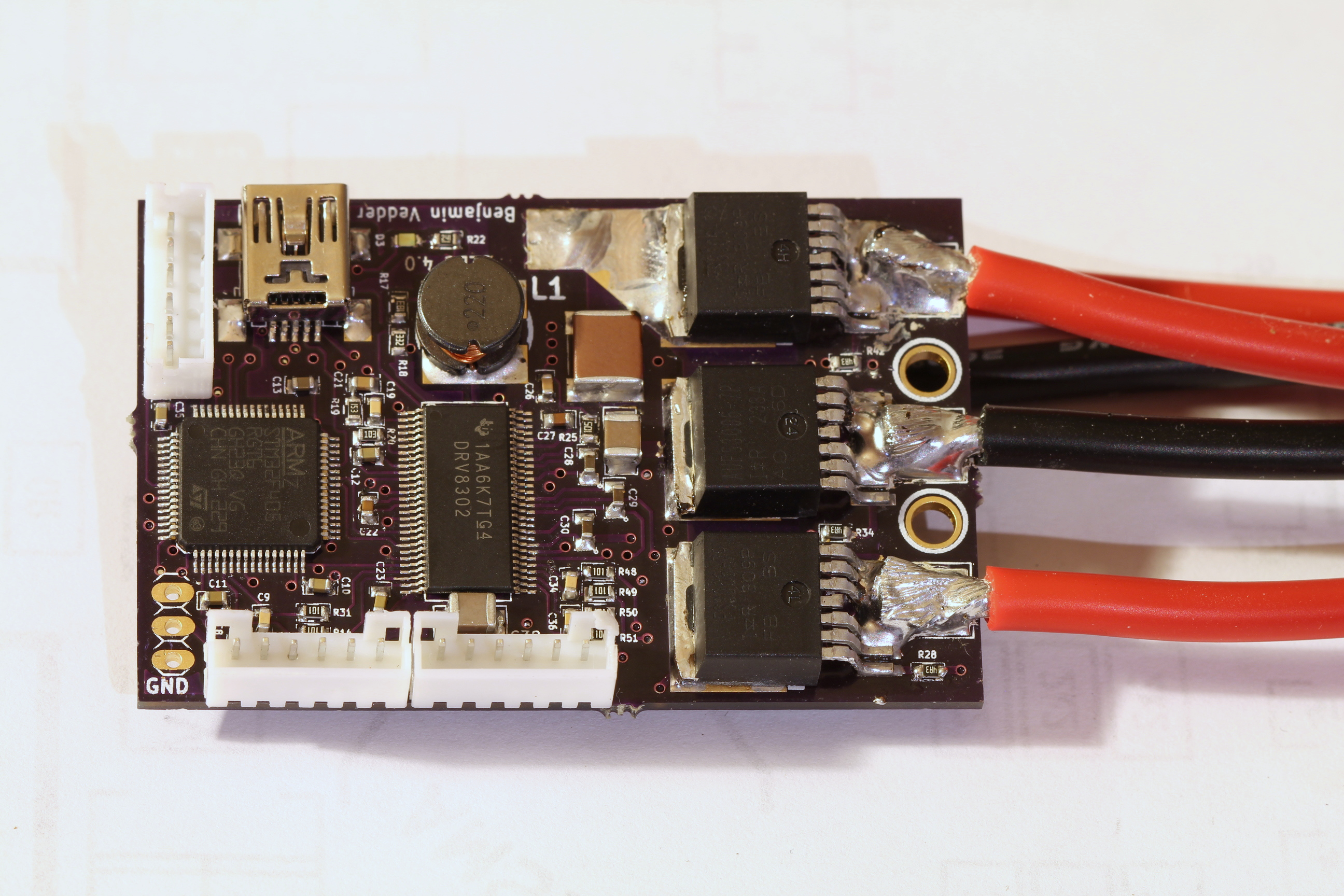
This is a photo of the front of the assembled PCB (please ignore the soldering quality…):
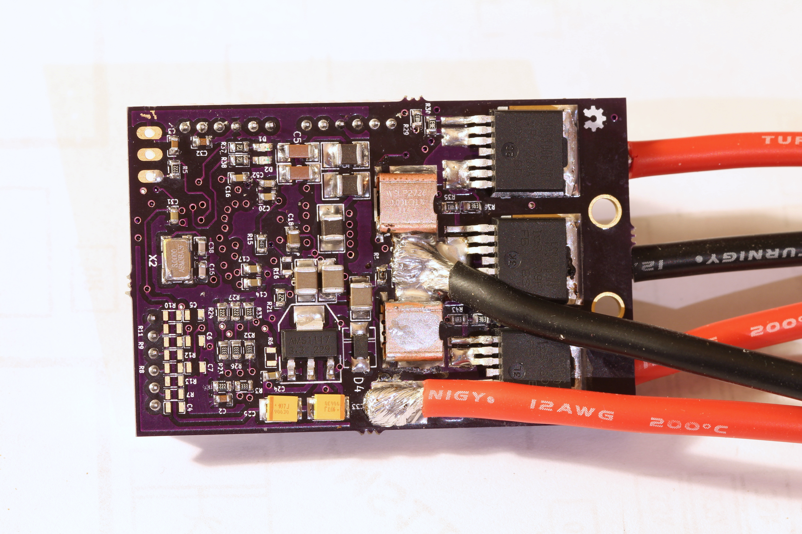
This is the back:
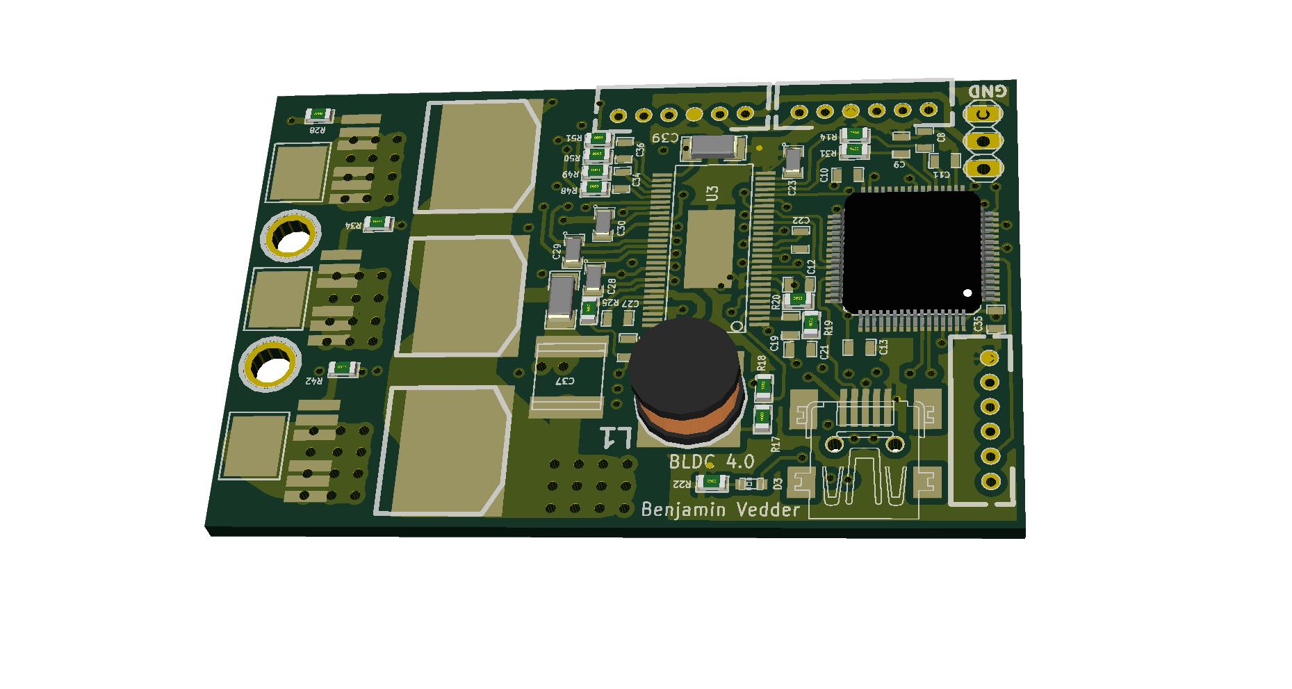
An image from the KiCad 3D-viewer
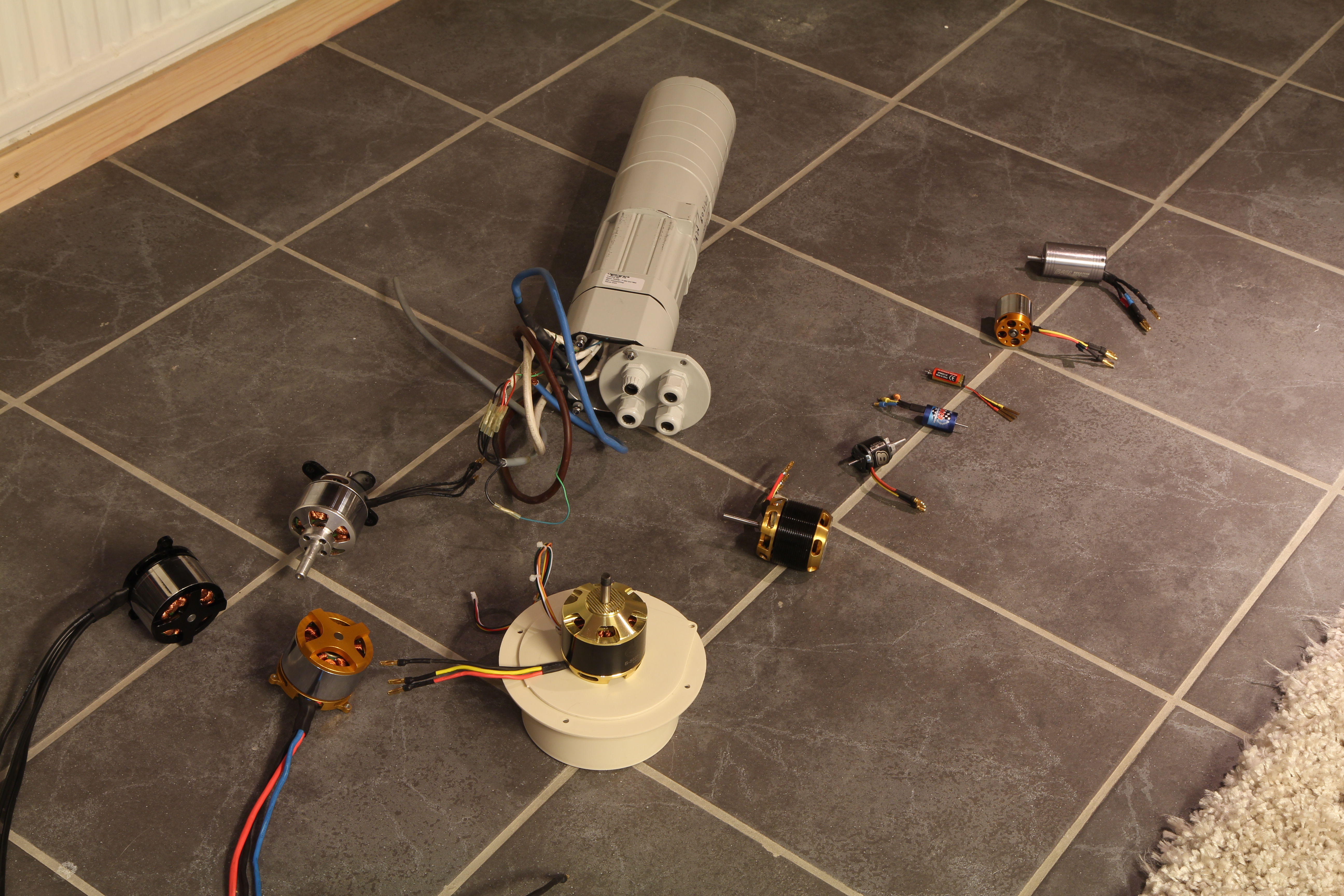
I have tested the following (and more) motors in sensorless mode and achieved good startup torque:
Issues and updates
Before presenting the details of the hardware design, I will present some notes and updates that have come to my attention while testing the motor controller. There are also some people worldwide who have rebuilt my motor controller and got it working after I helped them a bit, so I have also added the issues they have encountered here.
* UPDATE * I replaced the 3.3V regulator with the TC2117-3.3VDBTR and got rid of a few problems. The dropout voltage on the other regulator was probably too close to the difference between 5V and 3.3V, so sometimes the 3.3V supply would drop.
* IMPORTANT UPDATE * Replace L2, L3 and L4 with 0 ohm resistors. Otherwise, the DRV8302 will keep dying randomly. NOTE: This is fixed in the latest hardware versions on github. I strongly suggest that you use one of them.
* UPDATE * If the motor controller resets when drawing large current spikes, the cause can be that the buck converter shuts down for a while. I noticed this on my RC car when I set the current limit to 150A. I solved that by removing C26 from the SS_TR pin on the DRV8302. This will disable the slow start feature of the buck converter, which makes it start up fast enough after shutting down for the microcontroller not to shut down. I don’t know if this is a proper solution, but it has been working for the few hours I tested the RC car without problems.
* NOTE * The pad under the DRV8302 has to be soldered. If it isn’t, the motor controller will not work for sure. The pad is not just for thermal cooling, it is also the only ground of the DRV8302.
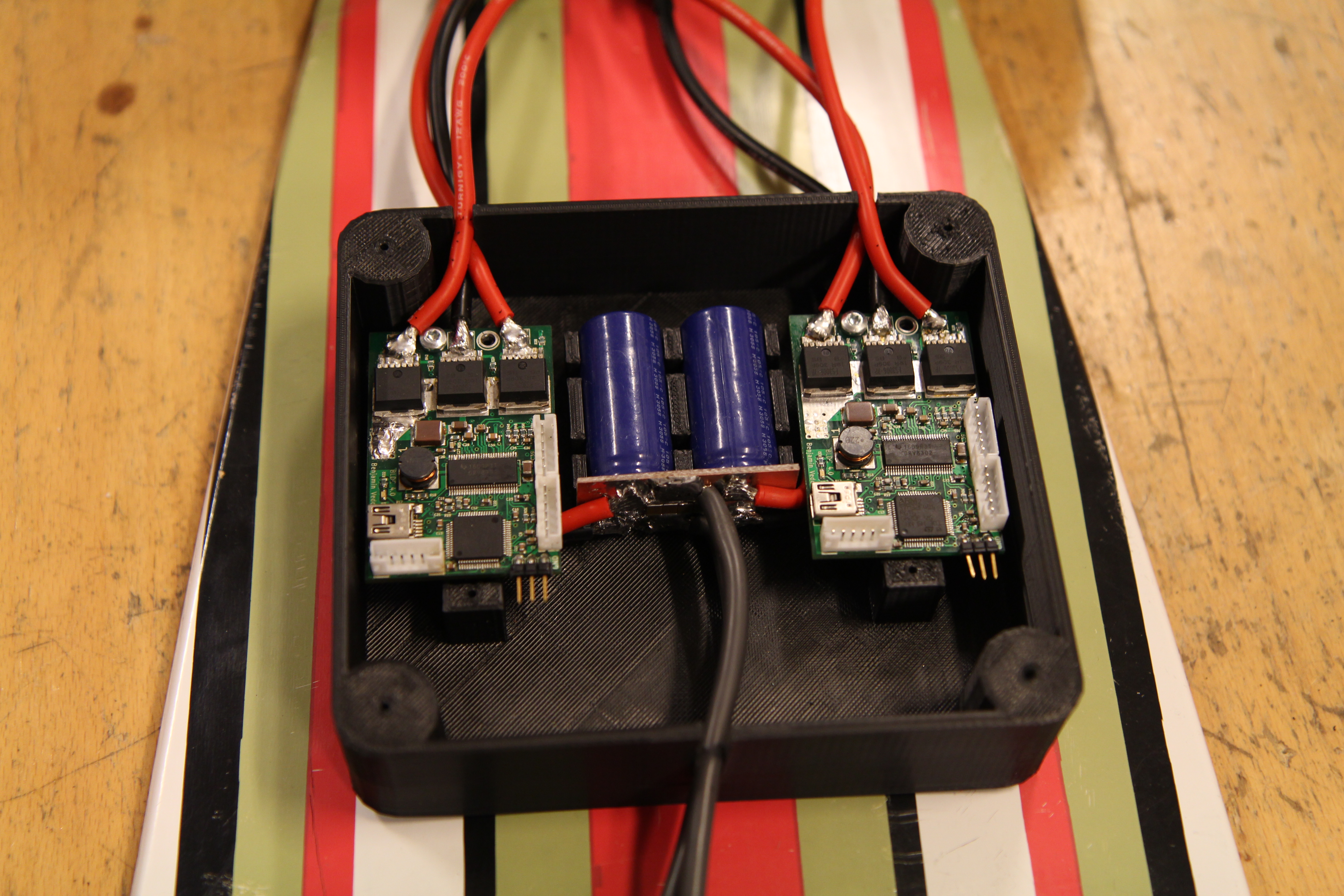
* NOTE * There are no electrolytic capacitors on the PCB, only small ceramic ones to handle high frequency noise. However, there should be rather large electrolytic capacitors close to the motor controller on the DC bus. I chose not to put them on the PCB to make design a bit more flexible. For example, one can add capacitors like this:
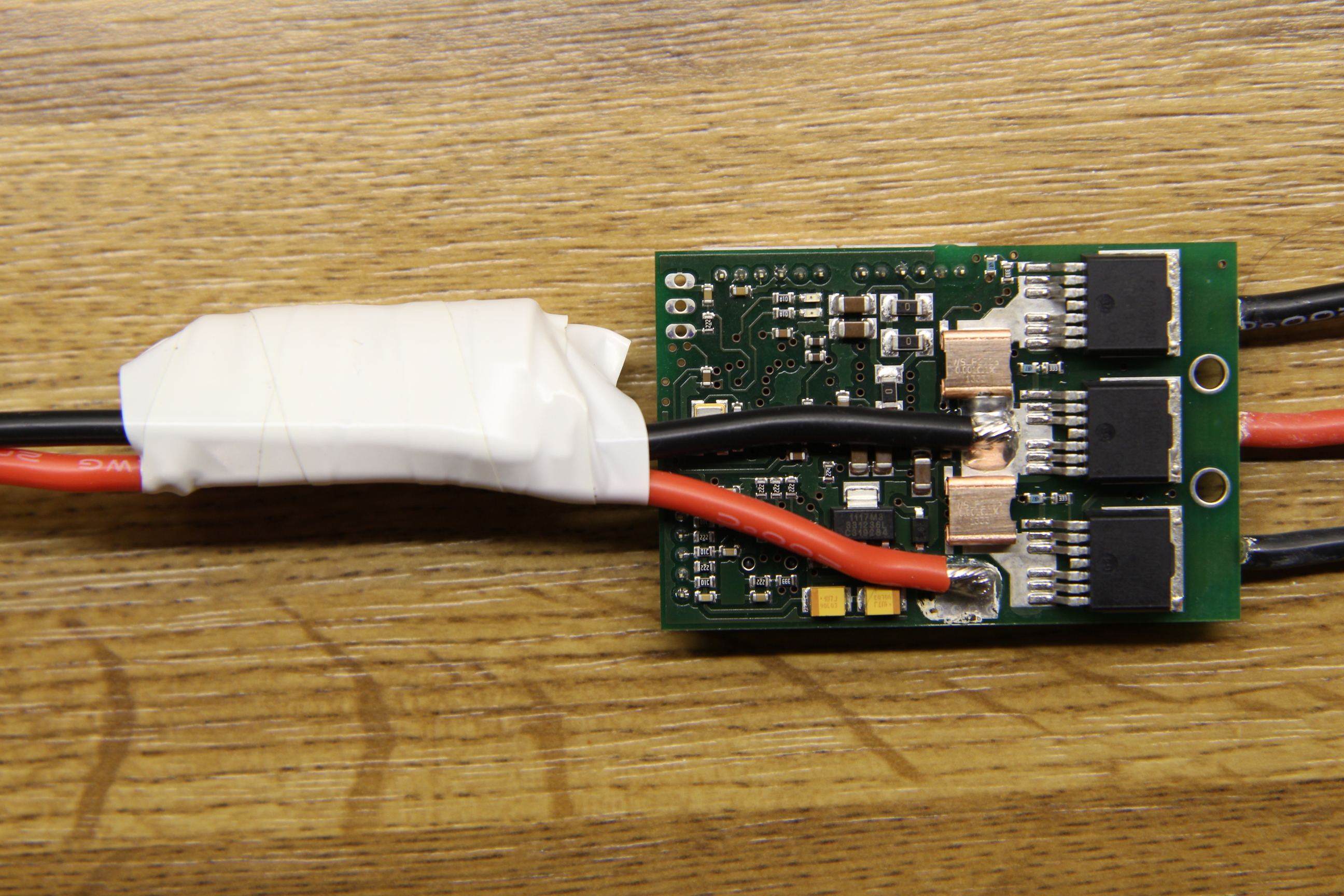
for a multicopter, it might be a bit more convenient to put a capacitor on the cable like this:
Hardware design
IMPORTANT UPDATE: A new version of the hardware can be found here: https://github.com/vedderb/bldc-hardware I will write a new post about that and the large amount of recent updates soon. If you want to build this motor controller, please use the hardware from this github link since it has many important fixes and features. There is also a new BOM linked from github.
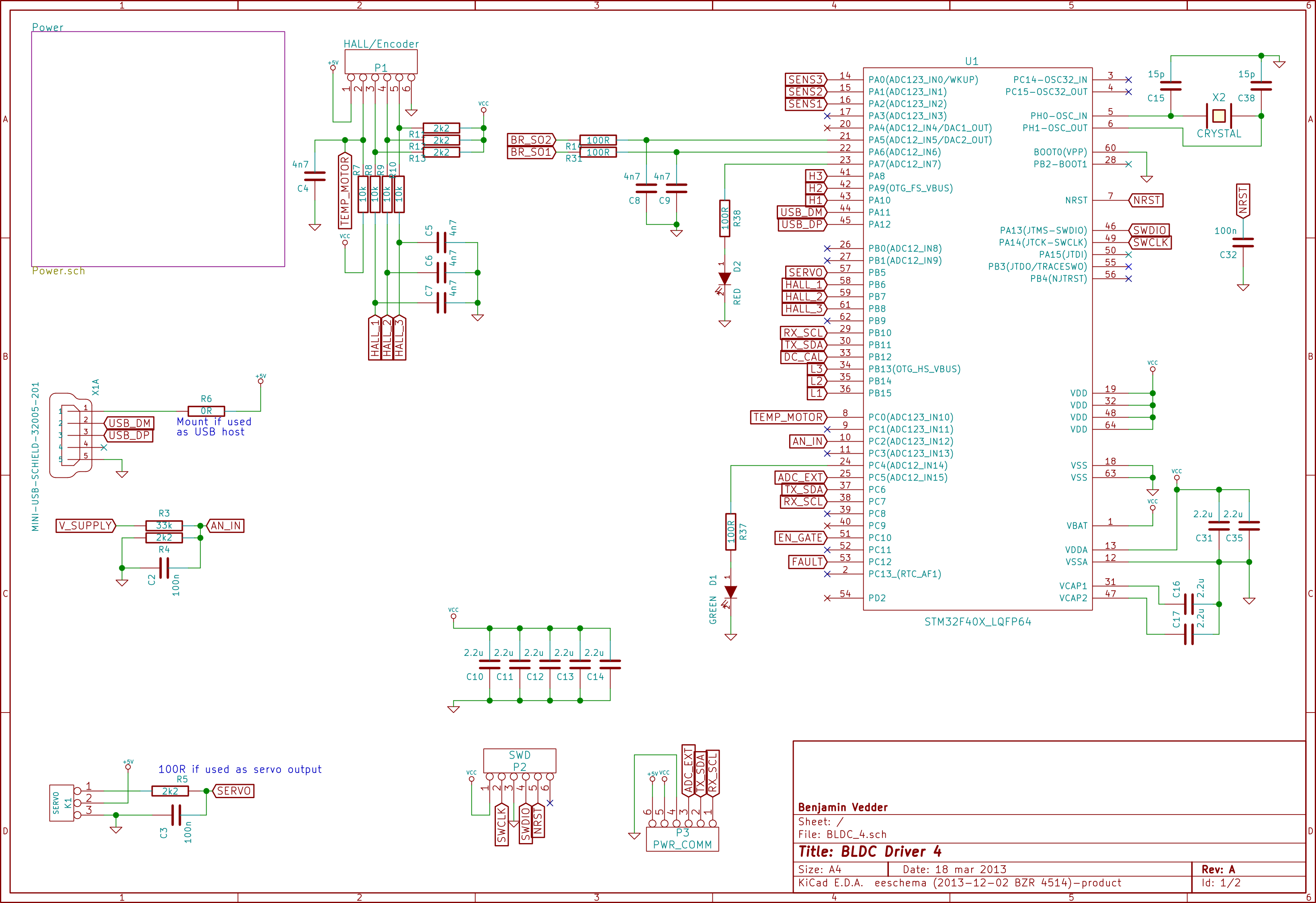
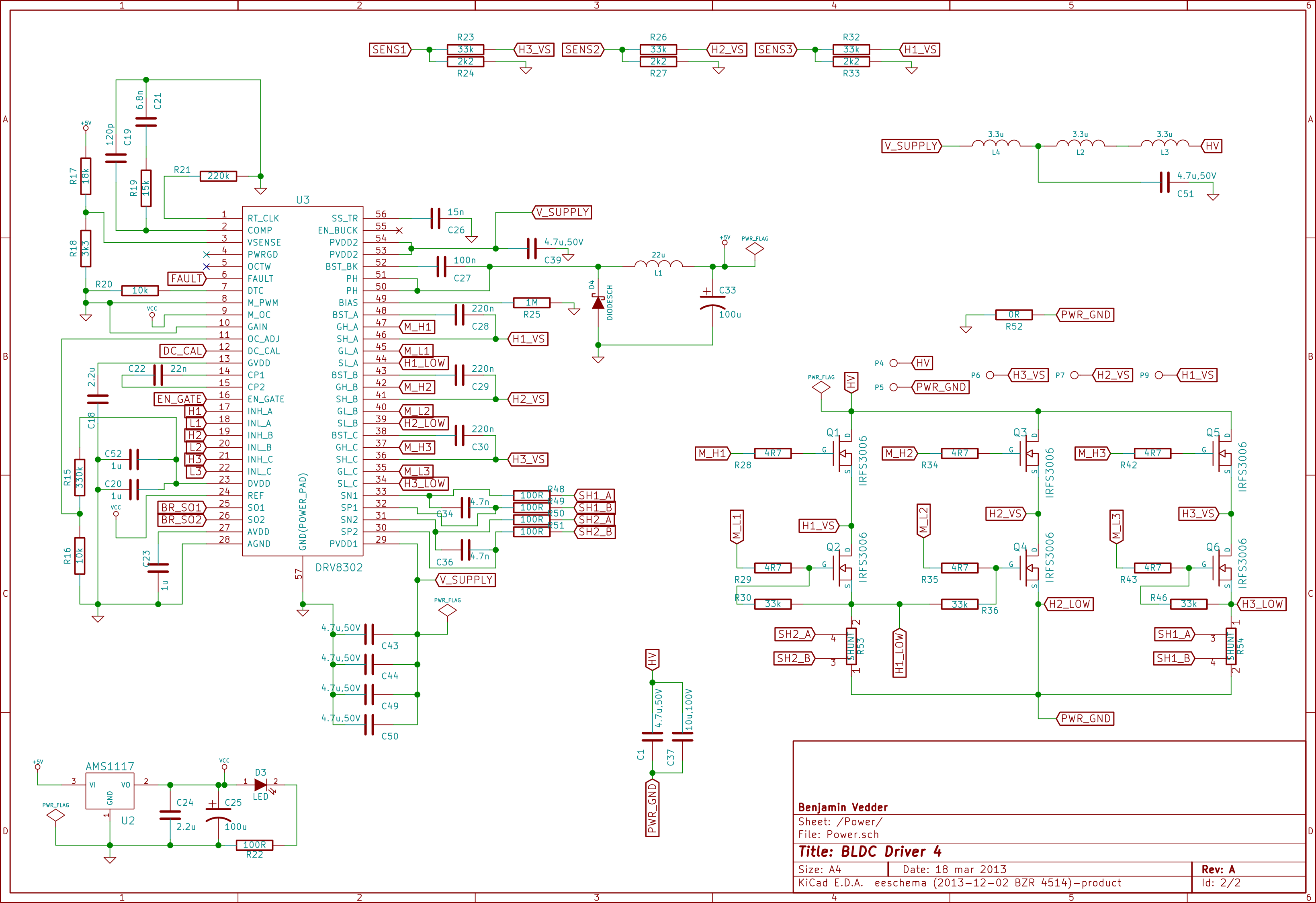
The PCB has four copper layers and is designed with KiCad. The size is slightly less than 40mm x 60mm. This is the schematic (a PDF can be downloaded here):
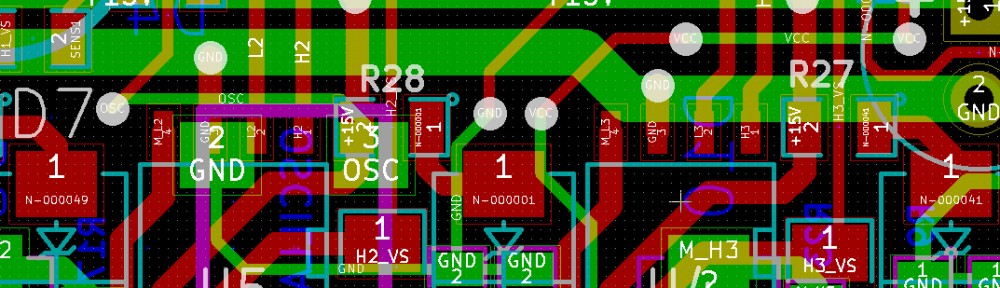
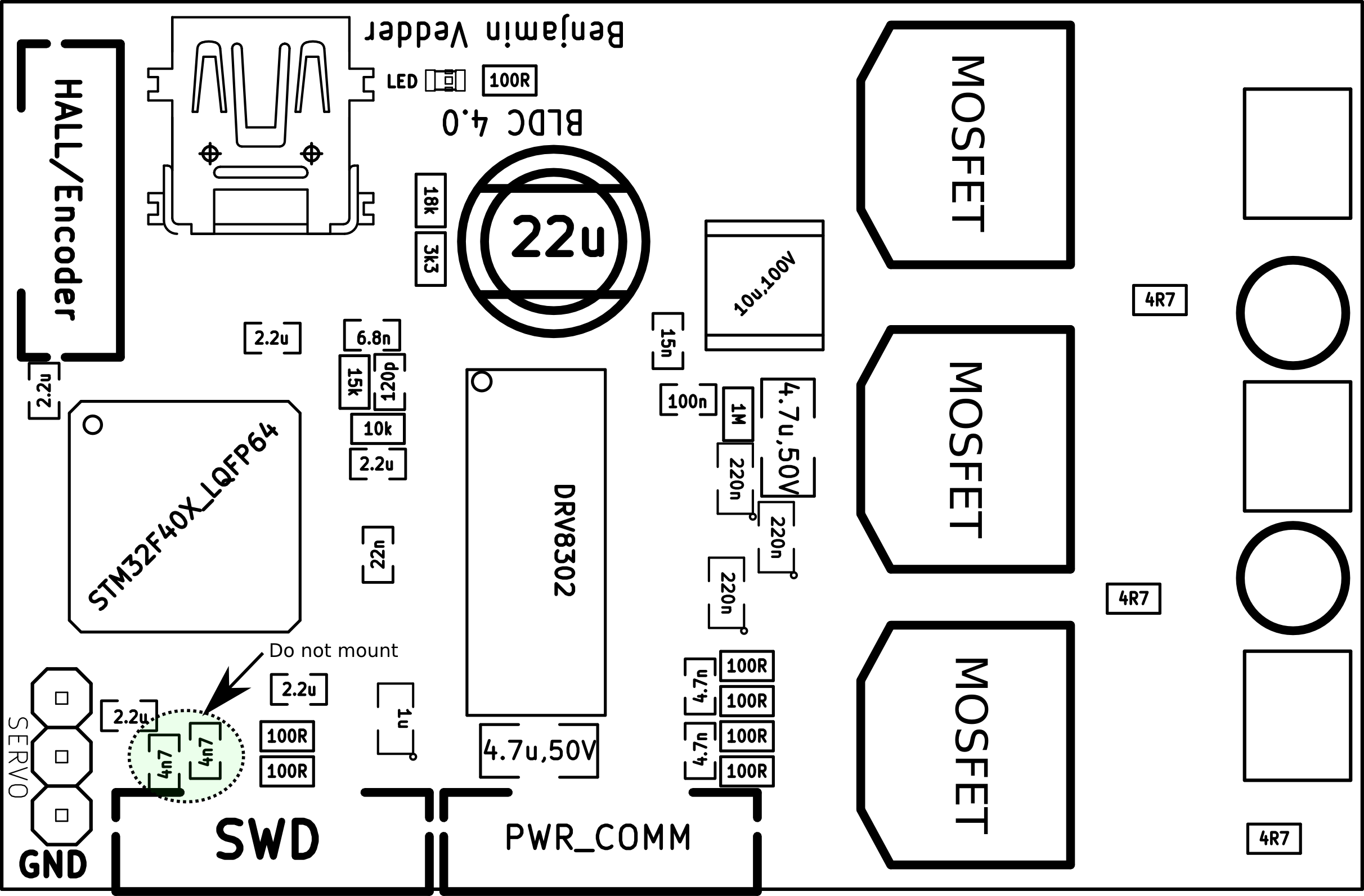
The component positions and their values on the front:
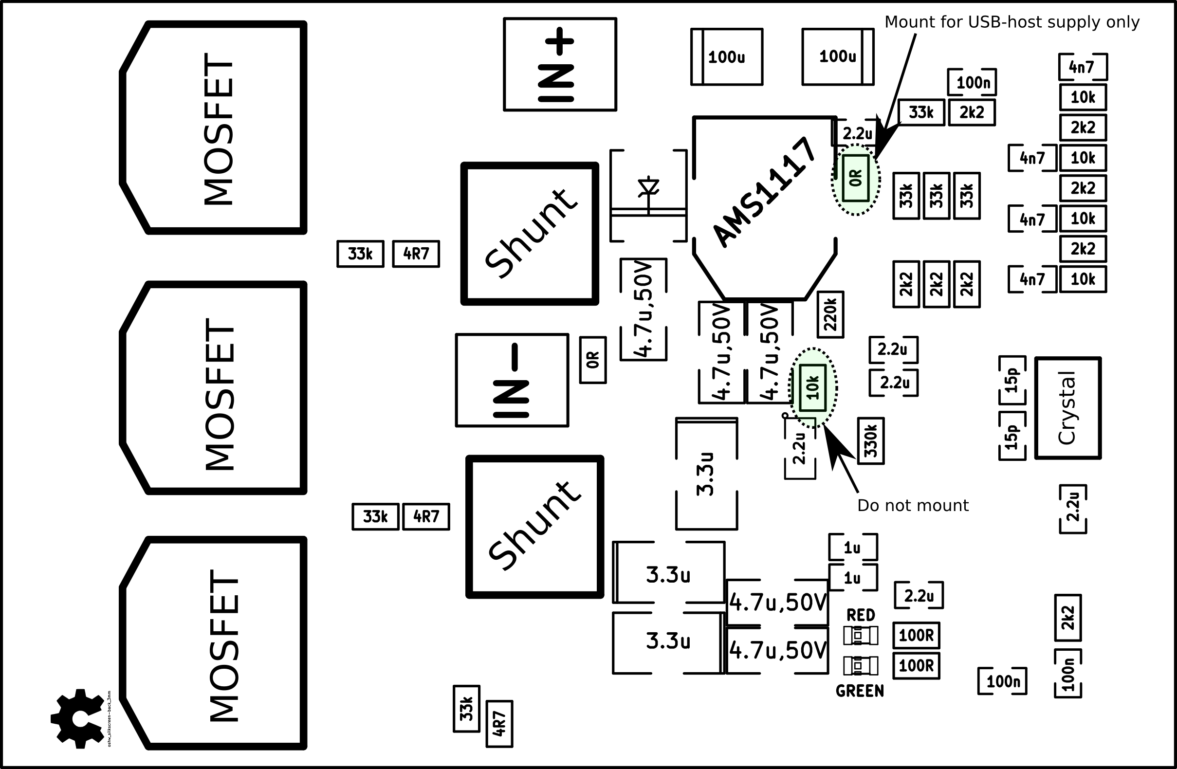
On the back:
A BOM with mouser part numbers can be accessed via google docs:
The KiCad-files can be downloaded here. If you are missing any KiCad libraries for this project, they can hopefully be found here.
PCB service
- The PCB-service from Hackvana works well for this PCB. In this case, use the following gerber files: BLDC4_Hackvana_v1.2
- The PCB service from OSH park also works well. In that case, use these gerber files: BLDC4_OSH_Park
Software overview
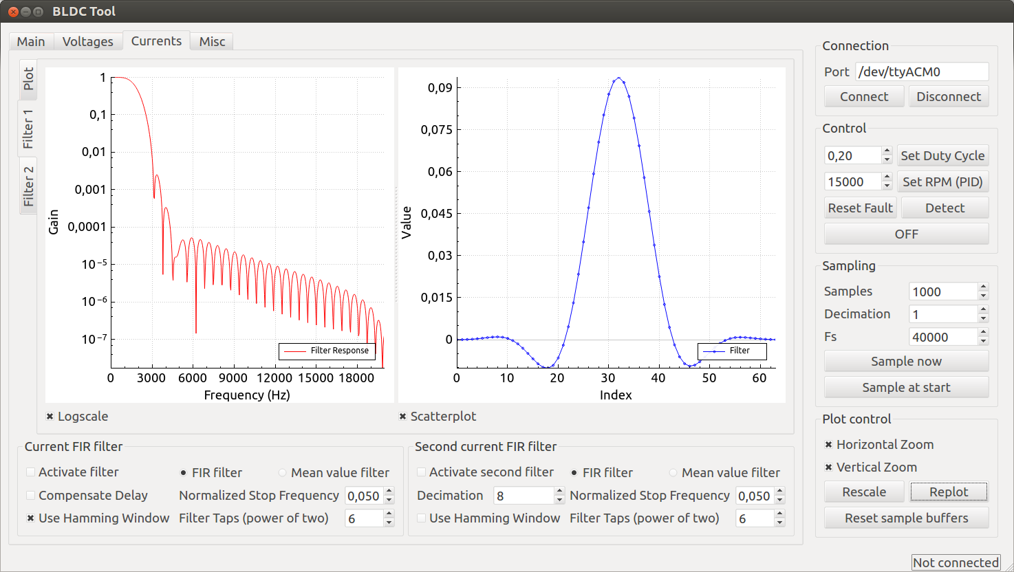
The software consists of a ChibiOS-project for the STM32F4 and a Qt-program to test and debug the hardware. This is what the FIR filter design part of the Qt program looks like:
It is possible to plot the currents, voltages and the duty cycle in real-time. This is useful when debugging how everything behaves when e.g. the software current limits are hit while loading the motor. Data can also be sampled and stored at a high rate internally and then sent to the Qt program for plotting high-speed processes such as the commutation timing. Here is a screenshot of the program displaying the commutation timing:

Note that the hall sensor position in the screenshot above is constant because there are no hall sensors connected. When adding custom hall sensors to BLDC motors, their position can be adjusted by comparing their output to the estimated rotor position in sensorless mode. Plotting the hall sensor position while running the motor in sensorless mode is therefore very useful.
Software set-up
The STM32 code for the BLDC controller can be downloaded here. In order to build and run it, ChibiOS with the ST libraries and a minor modification is required – you can download it here. To set up the required toolchain you can have a look at this post.
The Qt program can be downloaded here. To build it on Ubuntu (tested on 13.10), run:
sudo apt-get install qtcreator qt-sdk qmake make |
Now you should be able to start the program and connect to the motor controller.
A short tutorial to run a motor
In this section I will describe how to run an outrunner motor in sensorless mode from Ubuntu Linux. The reason for using an outrunner is that the parameters in the github project are tuned to work with most of my outrunners that I have at home. Adjusting MCPWM_CYCLE_INT_LIMIT in the mcconf file can affects the timing and should be tuned for each individual motor.
Note: The start-up torque in sensorless mode is higher than on most sensorless hobby ESCs, but the algorithm to start the motor will cause a delay before closed-loop commutation can be used. This delay is not desirable when e.g. building a sumo robot such as this one, so in such applications a sensored motor and the sensored mode is recommended.
Required steps
- Add your user to the dialout group as described here. Log out and log back in. This is done in order to access the serial port emulated by the USB interface of the motor controller.
- If you don’t any 3g modem on your computer, remove the modemmanager package. This is because otherwise there will be many seconds delay before the Qt program can access the USB port since modemmanager is interfering (I’m sure that this can be solved in some other way).
benjamin@benjamin-UX31A:~$ sudo apt-get remove modemmanager
- Install a toolchain for compiling and uploading the STM32F4 code. See this post for a tutorial.
- Download the ChibiOS-version with a minor USB modification: ChibiOS-RT-master. This modification disables the voltage sensing on the VBUS pin because that pin is used for something else.
- Compile and upload the program to the motor controller. How to use a discovery board as a programmer can be seen here.
- Assemble the PCB. The component position sheets above are very useful for that.
- Connect the outrunner motor and a power supply to the BLDC controller.
- Download the STM32 code here. Set the path in the makefile to where you have extracted ChibiOS. Compile and upload the program.
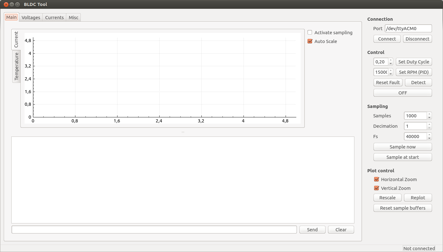
- Compile and start the Qt BLDC tool as described above or on the github page here. A window like this one should appear:
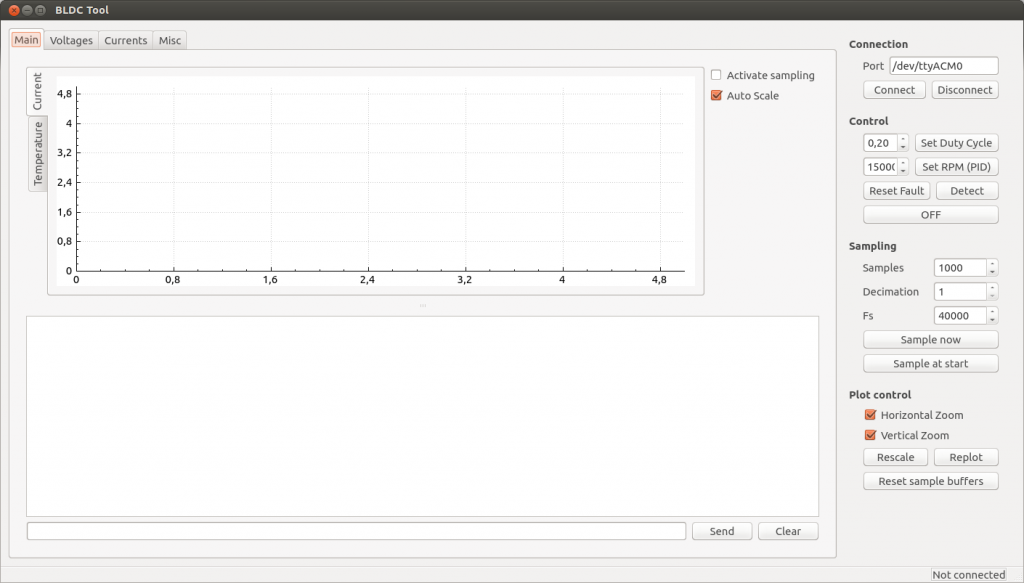
- Make sure that the USB cable is connected and the correct port is chosen in the tool, e.g. /dev/ttyACM0. If you have other devices that show up as serial ports, the BLDC controller might get another one such as /dev/ttyACM3. See the dmesg output when connecting the USB cable to see which device is assigned to it:
benjamin@benjamin-P5K:~$ dmesg | tail
[ 8198.248058] usb 1-5.3: new full-speed USB device number 6 using ehci-pci
[ 8198.357182] usb 1-5.3: New USB device found, idVendor=0483, idProduct=5740
[ 8198.357185] usb 1-5.3: New USB device strings: Mfr=1, Product=2, SerialNumber=3
[ 8198.357188] usb 1-5.3: Product: ChibiOS/RT Virtual COM Port
[ 8198.357191] usb 1-5.3: Manufacturer: STMicroelectronics
[ 8198.357193] usb 1-5.3: SerialNumber: 270
[ 8198.395006] cdc_acm 1-5.3:1.0: This device cannot do calls on its own. It is not a modem.
[ 8198.395038] cdc_acm 1-5.3:1.0: ttyACM0: USB ACM device
[ 8198.395503] usbcore: registered new interface driver cdc_acm
[ 8198.395506] cdc_acm: USB Abstract Control Model driver for USB modems and ISDN adapters
- Connect to the BLDC controller with the connect button. The lower right corner of the GUI should say Connected.
- Use the right and left arrow keys or the buttons in the GUI to run the motor. Activate the real-time sampling (with the checkbox in the main tab) to see the currents etc. in real time.
- Study the code and use/adapt the interfaces for your own application.

Hi,
I would like to order PCBs, are these gerber files tested on a PCB?
https://github.com/vedderb/bldc-hardware/tree/master/design/Gerber
I composed a zip file from them for OSH park:
https://www.dropbox.com/s/id6p8heug86th8z/BLDC.zip?dl=0
Looking forward to build an ebike and longboard with your controller.
I am working on a similar project, but for 400V industrial AC servos with resolvers with IGBTs.
https://github.com/rene-dev/stmbl
Here is a video driving a Bosch Turboscara:
https://www.youtube.com/watch?v=Ue98HE76paI
It will eventually be controlled by linuxcnc.
Thanks,
Rene
Hi Benjamin, I looked at different ESCs, Hobbywing Xerun, ESC32 and for the latter I even started to make some code modifications in the STM32 firmware.
I have the feeling yours would be the better start though as the ESC32 is meant for multirotor and I have a car like application. I have browsed through the source code and my main additional requirements would be
1. Closed loop down to zero rpm with a sensored outrunner. The intention is to have super smooth low speed operation and active breaking. To be more precise
1.1. The motor startup should not spin the motor to a minimum rpm, it should use forced commutation initially and then switch to proper commutation. I have seen that in sensorless mode you do have a min rpm.
1.2. Requires active breaking, imagine the car would roll downhill by itself with 100rpms, the target rpm is 20 or even zero. So it needs to break actively using regenerative breaking as long as possible and a zero speed apply an initial break force.
2. As silent as possible. This is the area I am uncertain but a sinusoidal PWM I would have high hopes for.
Anybody interested in joining forces? Anybody interested in a cablecam camera rig?
Would greatly appreciate your thoughts
-Werner
Oh, if somebody has a spare board ready to run (I cannot solder SMD) for sell, please contact me.
http://wdaehn.blogspot.de/2013/11/a-different-perspective-filming-with.html
Do you consider making a position servo controller with the FOC library ?
Hi Benjamin,
Congratulation ! You made a great piece of software and hardware.
Very impressive. Thanks for sharing.
I have a Nucleo STM32F401 and I’d like to make a shield for it based on your board to control an outrunner in a closed loop motion project.
It seems that we can get all the STM32F4 pins on the morphos connectors.
It will be usefull to use the STlink USB connection to run your nice Qt supervisor.
In which file is the port config for using PA2 and PA3 in place of PA11 and PA12 for USB ?
I have to redirect also SENS1 from PA2 to another free port.
I get an PARSE_ERROR on loading “BLDC_4.kicad_pcb” from GIT, but no problem with your pcb (from http://vedder.se/wp-content/uploads/2014/01/BLDC_4_KiCad.zip)
This is a very interesting project. I have an ebike application and was looking for suitable FOC controller for some time now, I even attempted my own project with AT90WPM3B (8bit AVR with advanced power stage controller). Found some purchasable controllers, but all of them are either too big or have too many problems, or both. Some explode on heavy startup, others have too low PWM frequency and can’t work with low inductance outrunners, etc… So I really hope you will succeed with this.
A short question about your MCU choice (STM32F4xx). To my knowledge, it has no analog comparators, meaning that cycle-by-cycle current limiting is harder to achieve and is being done in software. That usually adds some delays and could end up as a problem, especially with low resistance and inductance motors (for example 10mΩ 15μH). AFAIK, only STM32F303xB/C has this functionality in hardware. Have you considered this part?
hi:
i am a guy from china.i have read you code a few days ,but it’s a little diffuct for me to understand.so i wander do you have any tutorial about how you word.can you share me the tutorial that you have ,or the wedsite.thanks a lot. my e-mail address is shifm_od@163.com.thanks again.
I have built a controller but I have problem connecting it to
the usb port. I get the following error (dmesg):
[ 4450.108166] usb 5-1: device descriptor read/64, error -71
[ 4450.536095] usb 5-1: device descriptor read/64, error -71
[ 4450.752173] usb 5-1: new full-speed USB device number 41 using uhci_hcd
[ 4451.164079] usb 5-1: device not accepting address 41, error -71
[ 4451.276098] usb 5-1: new full-speed USB device number 42 using uhci_hcd
[ 4451.688055] usb 5-1: device not accepting address 42, error -71
[ 4451.688096] hub 5-0:1.0: unable to enumerate USB device on port 1
[ 4475.796186] hub 5-0:1.0: over-current condition on port 1
[ 4475.908175] usb 5-1: new full-speed USB device number 43 using uhci_hcd
[ 4476.028160] usb 5-1: device descriptor read/64, error -71
[ 4476.252175] usb 5-1: device descriptor read/64, error -71
[ 4476.468180] usb 5-1: new full-speed USB device number 44 using uhci_hcd
[ 4476.588161] usb 5-1: device descriptor read/64, error -71
[ 4476.812143] usb 5-1: device descriptor read/64, error -71
[ 4481.868188] hub 2-0:1.0: connect-debounce failed, port 1 disabled
[ 4484.552169] hub 2-0:1.0: connect-debounce failed, port 1 disabled
Any tips what could be the issue ? What to look for ? The board
seems to work – I can program the MCU, leds are running (blue – on,
red – off, geen on (low)).
hey jm,
did you get this resolved?
Was it a hardware error?
I happen to have the same error with the 2 esc’s I just soldered.
Hi,
I didn’t notice this comment before. Which HW version are you using? 4.0 does not have 22 ohm series resistors on the d+ and d- lines, and maybe that doesn’t work on some computers, although I haven’t experienced that problem on any computer myself. You could try a different USB port or with/without an USB hub. Also, make sure that R6 is not mounted.
It seems there are different issues I have to resolve first.
The red led blinks 4 times which corresponds to the FAULT_CODE_ABS_OVER_CURRENT according to the code in datatypes.h – but I’m only suppling the esc with 8.5v@100mA.
And on the 2nd esc the DRV8302 seems to be soldered incorrectly since it won’t light the blue led when connecting power.
Sorry, forgot to mention that it is hw version 4.0.
Dear Ben,
“This is due to the fact that the magnetic flux is integrated after the zero crossing instead of adding a delay based on the previous speed.”
Can you, please, explain a little bit more what exactly do you integrate and how the result is used in the commutation algorithm?
Thank you very much
Jerry
Here is a video from TI where they explain this a little bit:
https://www.youtube.com/watch?v=szgVUfyX8JM
It is not as simple as that though for most motors. Depending on how the PWM is done, there is some position-dependent voltage on the back-emf signal of the motor that makes a lot of difference at low speeds. Compensating for this is how I got good low-speed performance.
Hi,
Our school has a project regarding BLDC motor control. We are using the sensorless and the sensored bldc motor. Upon reading tutorials and forums regarding BLDC motors, I feel that I am still a novice in this topic. We will fabricate our own version of controller later this week. Is there a way that I can have a consultation with you?
Thanks in advance
Hi,
i assembled the board, programmed it and its running fine! Great job Benjamin!
I am wondering if i am doing something wrong with the motor detection function. It is not working as described.
When i press the Motor detect button, nothing happens for about 1sec, then a very short “tic” is noticeable and then i get a failure report in the output window.
Is there something i missed? i am running in PPM control mode with dutycycle control. I the fle “conf_general.c” i fount the function “conf_general_detect_motor_param”. Is this the one which does the Motor test?
Shall the PPM signal be zero when the function is invoked?
Why is there written “if(mcpwm_get_duty_cycle_now() < 0.6) {"sleep 1ms"}
Does this mean in case the dutycycle is lower than 0.6, the function does not work? Do i have to start the motor manually?
Nice that you got it assembled! To run detection, you have to disable ppm input because it will stop the motor as soon as detection tries to start it.
Detection runs the motor at the specified current until the duty cycle reaches 0.6, then releases it and measures the back emf. After that, it will run the motor at low duty cycle and measure the Coupling. This is not always working, so I will implement some other detection methods soon.
Hi Benjamin,
Awesome work!
I’m interested in what is the max MCU usage in %?
Best regards
Nick
Hi Nick,
At the highest switching frequency a rough estimate is around 50% based on the cycle measurement timer. The code can be optimized a lot, but I won’t spend time on that until performance becomes an issue.
/Benjamin
I asked about the MCU usage because I wonder is there a suitable MCU to drive 4 x BLDCs simultaneously?
Hi Benjamin,
Impressive work! I am currently doing a quadcopter project and I am going to build a motor controller instead of using ESCs. My motor is rated at 15A, 1100kv. I am planning to use DRV8301 with CSD18502KCS N-channel power MOSFET, and dsPic33E microcontroller. That would give me the max current at 14A. What do you think about this?
Also if I were going to use some of your technique, can I design 4 motor controllers in a single board? That means I have 1 microcontroller, 4 DRV8301/02, and 24 MOSFETs on a single board. Do you think it is possible or do you have any suggestion? And your continuous current is 50A, it would be too much to drive a 15A motor, what would you do to design a lower output current motor controller?
One more thing is that I am trying to draw the schematic using Eagle CAD, but I couldn’t find components such as DRV8301/02 and mosfets. Do you have any ideas to find these components library? I know you are using KiCad, and I’m considering using this too, but do you think I can find all the components in KiCAD?
Thanks so much.
Hi Benjamin,
And what a great project!
I’d like to know if you have knowledges of references (books, websites, articles) from where it is possible to a lot of the motor (bldc) specific information and strategies.
Especially information about designing driver circuits, and running the bldc most efficiently. I’v read a lot of different articles from IEEE and another database (i dont quite remember the name). It seems like i only get “half” of the facts from these articles.
I did make a BLDC controller which worked, not very efficiently anyway. But i’m about to design one for a larger project, for which i’d like some “professional” insight.
Hi Benjamin,
Great projects. I have trying to contact you for some help recently on “Leave a Reply” but not get through.
could you please advice how all the other correspondence got through?
The best regards.
Cool project! I’ve been looking into trapezoidal projects/examples, as the sinusoidal or foc is more than my 8-bit 8051 can handle. Long story 😉
I suppose pwm isn’t needed if you aren’t varying the speed/torque, but if you are, do you have any thoughts on the most common PWM techniques (bipolar vs unipolar, complimentary vs independent)? State space vector modulation (SVM)?
For example, I’ve read that for sensorless bldc, one should pwm both phases (bipolar), otherwise unipolar is better for emi.
In addition, if you need 4 quadrant (braking/regeneration) then both switches of a phase should both be pulsed (complimentary and with dead time of course).
But what if you don’t need breaking (or your dc supply can’t handle an average current fed back into it), is it better to use independent?
Also, someone on irc said the PWM switching frequency should be anywhere from 200hz (high inductance motor) to 64khz (low inductance motor) in order to minimize torque/current ripple at perhaps the expense of audible noise, and that the pwm freq should be at least 10x the commutating frequency, has this been your experience as well? Is there a max rule-of-thumb?
Also for a sensorless application, do you prefer sensing zero crossing, then using a timer to trigger the next commutation step, or do you prefer to integrate the back-emf voltage (flux) until you cross a threshold in order to integrate (i.e. the t.i. video you linked above)?
Wow, sorry for the long wall of text, but the more I think about motor esc, the more questions jump in my head!
I have implement three different PWM techniques and I prefer the synchronous one (having one switch on and pulsing between the upper and lower switch on the other phase). If you don’t want to use braking you can use current control and limit the current. I’m using variable switching frequency to get good samples at low duty cycles. For commutation, I have implemented both zero crossing with delay and integration (both with adjustable timing) and I prefer integrating the voltage because that works better at lower speeds. Integrating the voltage is a bit tricky at low speeds for some motors since some of the input voltage can be seen on the floating phase.
Hi Benjamin. I want to say an amazing project you have going. I do have an issue with the motor detection procedure at the moment that results in a fault code of under voltage. Im using 16 AA Energizer rechargeable battery,1500mAh, nimh chemistry since don’t have lipos at the moment. Motor as a test is 380Kv NTM 5060. I am also getting a fault with the DRV8302
Heres a link to the pic of what I have been getting after starting detection.
http://i.imgur.com/AHiRE0b.jpg
Thank you very much for your great development work and sharing.
I’ve read all posts and I have not found the answers on my questions:
1. Can I get with your ESC controller a speed reference from 300 rpm to 3000 rpm with an accuracy +/- 5 rpm ? my BLDC motor uses 48V and 3 KW power
2. Can I get the current rate per minute feedback from your ESC controller ? the better way for me is proportional analog output or bus.
Thanks 🙂
1. I haven’t measured the accuracy and it depends on the application, but it should be possible.
2. You can read it over CAN, USB or UART, but there is no analog output. What do you mean by bus?
thank for your fast reply and you are quite right!
I mean that this is the bus CAN or UART
Hi, Is there any way to run Bldc motor without ESC ? I want to run my Turnigy XK1222 at maximum speed all times. I don’t want to use receiver and transmission.
Hi,
No there is no way to run a BLDC motor without ESC because you need a 3-phase rotating system to spin the motor.
Regards,
Tobias
Will this controller suitable for my 48V 2000W BLDC hub motor (for ebike)..?
Hi,
Yes, a motor like that should work fine with this controller.
Hi Ben,
first of all : impressive ! good job!
For my electric mountainboard I would like to use your development.
Big question: Do you know someone that can deliver the complete VESC? including all the components already assembled on the PCB? How much would be the price?
Best regards,
Stephan
Hi Benjamin,
This project is definitely amazing and educational!This is the best tutorial to turn BLDC/FOC theory into practice.I’ve been looking for a ESC to implement BLDC and FOC control for a long time.I started with the ESC32 first but turn out it doesn’t have shunt resistors but a “overall” resistor to detect all the current go through the mosfet,which is impossible for FOC control.Besides,the hardware is not opensource and there are a little documentation or comment about the code.So I guess the two ESC32 boards I bought are useless to me now.But I decided to follow your tutorial!That’s so awesome!:)So do you have any spare board on hand and would like to sell it for me?I thought about order the components and blank pcb but when I checked the components on Mouser I realized it’s not that easy and it may take a month or so to make the first board run.So would you help me please.I know soldering is very time consuming so if you have the components and blank pcb I can do the soldering job.If you cannot sell it to me somehow I will still donate for you as I’m very grateful for your brilliant work and opensource spirit! Looking forward to your reply! 😛
Regards,
Malcolm
Hi Benjiamin,
I checked your schematic and I think I found the reason why the R16 resistor causes the faults.DRV8302 has two over-current protection modes,that is current limit mode and lath shut down mode.In your shcematic,you connect M_OC to vcc,but if you want to use the current limit mode you need to connect pin M_OC to ground otherwise you set the driver in lath shut down mode,which is reason why the mosfets are turn off frequently.But this is a guess,you may verify this by observing the pin OCTW,which is the pin that reports over current error.You can find detailed information on page 13 in the datasheet.
Another thing is that I suggets you to add the thermal via array under the DRV8302 driver as this is required by the datasheet.The dimension info can be found in TI application notes SLMA002 and SLMA004.
Malcolm
Hi,
I have tried connecting M_OC to gnd as well and it still has the same problem. I don’t know what the cause is, but it could be because the DRV8302 isn’t designed to drive these kinds of MOSFETs.
If you’ve already tried that,then I don’t know what would be the cause.Have you tried DRV8301?It’s similar to DRV8302 but it has a SPI interface to set the parameter and more current gain option,otherwise they are identical.And the prices are pretty much the same.Also,you could compare your board with BOOSTXL-DRV8301(http://www.ti.com/tool/BOOSTXL-DRV8301) and maybe you can find some clues.TI has released the schematic/layout on that website so actually I’m designing a new driver board based on your board and BOOSTXL board.Thank you for your work!
Malcolm
Dear Benjamin,
I’ve a question according to the use of the VESC in regenerative breaking mode as you discussed here with Alvaro on August 2nd-4th, 2014 who likes to charge a baterie with th VESC. Two days later you wrote :
“The braking mode actually switches the MOSFETs exactly the same way as when accelerating, but with a duty cycle that is lower than the corresponding back-emf voltage of the motor. This works because the switching mode is synchronous. This way, the motor windings will be used like the inductors in a boost converter and the current/voltage can be controlled quite accurately. However, if the motor is driven faster than the corresponding battery voltage, the body diodes will start conducting no matter what. Therefore you have to make sure to use a battery with high enough voltage.”
How I’ve to understand “…if the motor is driven faster than the corresponding battery voltage,…” ? Is it just the easy kv calculation kv*rpm must be smaller than the batterie voltage V_batt, or must the duty cycle be taken into account? kv*rpm*duty cycle kv = 60Hz * 60sec/min * / 14 / 5V = 51.5. Batterie voltage is 12V. The maximum speed in generator mode is 3000 rpm, what shoul give about 58V.
Will the battrerie be destroied due to the too high voltage or is it possible to reduce the voltage by reducing the duty cycle to e.g. 25% by wiriting a custom application?
Thanks for help
maxi
Maxi, if the motor is driven so fast that the back emf rises above the battery voltage, the battery will charge no matter what you do with the duty cycle. Decreasing the duty cycle has the opposite effect – it will increase the voltage output when acting like a generator, which is why you can use regenerative braking down to very low speed. When you construct a system with a battery and generator, you have to make sure that the generator output (RPM / KV) does not rise above the battery voltage. The are some tricks that you could do with FOC and field weakening, but it will not help much in the general case, and it will waste power. I also recommend using higher battery voltage than 12V to make the VESC and the rest of the system more efficient.
Hey Banjamin,
thanks for the fast replay!
As the VESC provides a huge current I can reduce the number of windings by a factor of about 4.5. Then I’ll end up with ~13V (LiFePo4 batterie) and a kv of ~11,5. Do you thing the VESC can handle such low kv?
Thanks in advance
MAxi
Hi, Could you give me information where i can get the complete VESC? I need it fast. Thanks
I can’t get it run, Is that the firmware need to compile under Liniux system? Is that any easy way to download the ESC code like bin and Hex?
Have you tried obtaining a sin wave as output to give the motors?
Hi vedder, is there a way that i can use this controller like a regular ananlog one for example 0V-2.4 Full forward 2.4-2.6V Full break 2.6-5V Full reverse.
Yes, that is what the ADC app is for. The total range is 0V to 3.3V though.
Hi Benjamin
I’m building a linear 3 phase BLDC motor and would like to know if I can run this closed loop but at really slow speeds about 0.5mm per second with your controller?
Regards
Trenton
Hi,
Does your code include high frequency injection method?
Dear Benjamin,
I soldered my board everything is OK and config BLDC Tool works well, but went I connect a small load the drv8302 had died, and I used alot drv8302 but all of it have same problem, I don’t know what reason is???.The difference between my project and your app is 2200uf 50V panasonic capacitor and schottky diode, and I think the problem is schottky diode, do you think so??? schottky diode using to current isolation between FET power and driver power, don’t you?
And anyone have a same problem can help me
Thanks in advance.
Hi, Ben
Awesome project! I was wondering if you could give a little bit more information on the algorithm to estimate armature resistance and inductance?
I tried reading the code, but inductance estimation is not clear to me.
Thanks!